68kMLA Classic Interface
This is a version of the 68kMLA forums for viewing on your favorite old mac. Visitors on modern platforms may prefer the main site.
| Click here to select a new forum. | |
| IIfx Memory | |
| Posted by: campbellashe on 2026-03-19 15:14:37 As I'm new to the IIfx, I'm trying to find memory for this computer as I only have a total of 8MB, what is the landscape like? It looks like given the unique 64 pin 70/80ns DIMM requirements, that they are hard to find. No real listings that I can easily find. Has any one made them? I did see a schematic on GitHub.... Or are there people out there with 4MB DIMMs willing to sell? Would love to get to 16 MB or 32 MB if able. Thanks. | |
| Posted by: joevt on 2026-03-19 16:12:40 There's this: https://github.com/hanshuebner/maciifxsimm I haven't tried it. | |
| Posted by: finkmac on 2026-03-19 18:14:42 i made some of those, they work well. | |
| Posted by: campbellashe on 2026-03-19 18:17:43 Thanks @finkmac I've been able to create the Gerber files from the GitHub site above. Priced out the creation of the PCBs on JLCPCB for around $7.00 for 15, and the stencil for around $16.00. The slow shipping is about $18... would need to source the chips -- can get the KM41C16000CK chips from UTSource for about 50 for $50 dollars. I've just never used stencils before... just don't want to get too far down this.... however if memory is un-obtainable then this might be the best route. Glad you were able to create them.... does this pricing seem right for your prior project? Did you use stencils? | |
| Posted by: finkmac on 2026-03-19 18:37:52 just remember to choose the right thickness. as the github project says, it's best to use a reflow oven type soldering process... that does indeed involve the stencil. | |
| Posted by: campbellashe on 2026-03-20 15:48:16 On the V2 of the PCB of the Gerbers (if you plot and generate through KiCad) there are now small capacitors indicated above each chip....anyone know the value of these? | |
| Posted by: campbellashe on 2026-03-20 18:33:41 I think the capacitors are standard decoupling/bypass capacitors with 0.1 uF values? Just checking. I wrote Hans Huebner to ask. 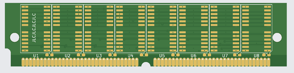 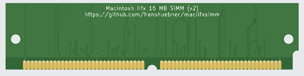 | |
Posted by: finkmac on 2026-03-21 21:54:17I think the capacitors are standard decoupling/bypass capacitors with 0.1 uF values?correct. I can't remember the exact part number I used, but that should be the right value. | |
| Posted by: campbellashe on 2026-04-08 07:47:02 Well the journey to create 16 MB SIMMS was successful.... now at 128 MB in the IIfx. Used the above git and printed at JLCPCB with a stencil (make sure the 1.2 mm size is selected on the board options) -- worked great. Just used a credit card to spread the paste. Used the SAMSUNG KM41C16000CK-6 from UTSource Used the Cap 0.1uF 50V Z5U 0805 for the capacitors (Digikey: 399-C0805C104M5UACTUCT-ND) -- small little buggers.... Lots of trouble shooting with continuity of the pins with the solder paste and looking for bridges. As well as just getting the SIMMs to sit properly in the slots. It was hard to troubleshoot the first 4 as they all had to work. Once a stable 4 then you can swap out the last 4 into the mix to narrow down any problems. Lots of fun... 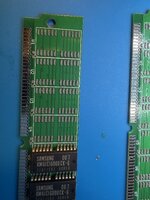 [td] [/td] 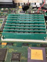 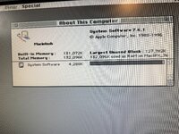 | |
| Posted by: finkmac on 2026-04-08 08:09:06 excellent work! i assume you went with the reflow oven method? what kind of oven did you use? As well as just getting the SIMMs to sit properly in the slots. It was hard to troubleshoot the first 4 as they all had to work. Once a stable 4 then you can swap out the last 4 into the mix to narrow down any problems.this was the biggest annoyance. I ended up having to tin the contacts a bit. | |
| Posted by: campbellashe on 2026-04-08 10:10:38 Actually, I used hot air and worked well. Things I learned: A) I set the hot air to 360 and flow at 30, worked great at about 4-5 cm above chips. B) I first tried to use hot air for all the components, but the capacitors blew off… I therefore moved to soldering them by hand. I have a microscope and a needle nose for my iron to get into the small space between chips C) tested continuity on all pins if error D) tested pairs to see if bridges underneath the chip E) the contacts were an issue, I had to reseat them multiple times - even a little solder bump can cause an issue F) I was worried about the Z5U a bit but they worked fine, make sure to get the 0805 size. G) using Kicad I did use the pcb view to network the traces some. But just checking GND and VCC and looking for shorts found most problems Overall a fun project. The chips were the most expensive part other than shipping and tariff fees. Thanks to Hans Hubner for his great design and git depository. I wrote him and he confirmed the capacitor value. | |
| Posted by: CuriosTiger on 2026-04-08 15:31:25 Excellent work. I have 20MB in my own IIfx, and have decided that will have to do. My second IIfx has 8MB in it. | |
Posted by: finkmac on 2026-04-09 05:36:01B) I first tried to use hot air for all the components, but the capacitors blew off… I therefore moved to soldering them by hand. I have a microscope and a needle nose 🤣 been there... it's easy to forget you're using AIR and not a funny heat beam. 🤔 you know, there's a lot of space in the IIfx case... could probably rework the simm designs to make them larger and easier to hand solder. the tradeoff would be more expensive pcb fabrication costs... | |
Posted by: trag on 2026-05-19 21:45:05🤣 been there... it's easy to forget you're using AIR and not a funny heat beam. Put every other chip on the back of the board.   | |
| Posted by: trag on 2026-05-19 21:47:56 This design is even easier to solder...   | |
Posted by: gsteemso on 2026-06-30 19:53:18This design is even easier to solder...@trag, do you have gerbers, part lists, etc for this alternate design? | |
| Posted by: Unknown_K on 2026-06-30 20:40:51 So, what does a set of 8 home built simms run these days? | |
| Posted by: campbellashe on 2026-07-01 07:32:34 The chips are expensive; from UT source I spent around $100 all in ( with shipping) for 64 chips - KM41C16000CK were at around $1 per chip. The caps and boards were about $50 all in to include the stencil — from jlcpcb. This was in April. At bit higher for the chips now. Still a fun project. i like the board designs above for ease of soldering, but stencils make it work.. would need to price the chips needed as that would impact cost. | |
Posted by: trag on 2026-07-03 02:45:10@trag, do you have gerbers, part lists, etc for this alternate design? I don't seem to have the Gerbers on line. It would be a bit of work to get them uploaded. I do my layout in Osmond PCB on a Mac running Classic. The memory chips are 16M X 4 FPM or EDO chips. The two smaller chips are a some kind of bus switch. It's been so long, I'll have to look at the design to see what I used. And there's one 5 pin logic gate I used to control the bus switches. The bus switches are needed because the Mac IIFX divides the Data Bus for RAM into separate Write and Read Data busses, instead of just using the same connection for everything. Actually, come to think of it, the Gerbers include one of each type of IIfx SIMM, the 16 chip and the four chip attached along the top edge. I did this because I had a coupon that was only good for one design, back in the dark ages when PCB fabrication was a $1000+ prospect. If you look closely there's a bit of irregularity along the top edge from sawing them apart. There was a thread all about this design somewhere around here, unless it was lost in one of the crashes. | |
| 1 |