68kMLA Classic Interface
This is a version of the 68kMLA forums for viewing on your favorite old mac. Visitors on modern platforms may prefer the main site.
| Click here to select a new forum. | |
| 48MB in a PowerBook 500 Series – an Illustrated Guide | |
| Posted by: croissantking on 2026-01-30 06:50:27 A few months ago, I worked out how to run 48MB in a PowerBook 500 Series. Inspiration was taken from Toyoki's 64MB mod for PPC upgraded 500-Series notebooks. The concept is similar – tap into unused RAS lines on the memory controller to bump maximum RAM above 36MB. Spoiler content hidden. You will need:
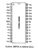 Here's my RAM card with 6 of the 8 new chips soldered down, and a 7th in position. You can hardly tell they are stacked. Note the two lifted pins per chip. 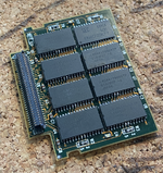 Here's a side view of the stacked chips soldered down. 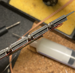 Use repair wire to connect up the RAS pins across the four chips at the top, and another repair wire to connect up the other four chips at the bottom. Don't connect them together! Run two trailing wires (one from each bank) to the RAM card connector. I left the NC pins floating/disconnected. Pins 28, 29 and 30 are labelled 'reserved' (more on this in a bit) in the Dev Note, page 35. I used pins 28 and 30 to send my RAS signals back to the CPU card, as shown: 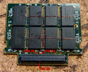 That's your RAM card done. Now, take your CPU card, remove the onboard RAM, and run two repair wires as shown to pins 190 and 191 of the Pratt MemIC. Make a cut on the trace leading out from pin 190/RAS0. 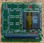 Side view of RAS0 (Pin 190) and RAS1 (Pin 191), showing repair wires soldered on. Definitely a fiddly job. 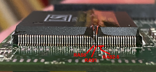 Moving to the RAM card connector on the top side of the CPU card, we need to peel back the serial# sticker and cut the traces leading to Pins 28 and 30 as shown. These go back to unknown pins on the Pratt MemIC, but aren't needed. @demik theorised they could have been used during development for ROM cards. 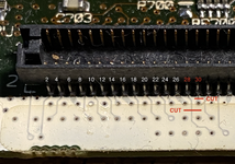 Finish by running your repair wires up to the pins. 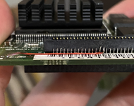 Assemble your machine, and there you go – 48MB in a PowerBook 500 Series. 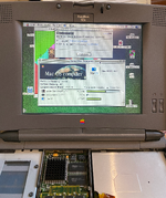 This was one heck of a difficult mod to do, it took me two attempts! Worth it though. I'm hoping to eventually create a 500 Series 'Reloaded' CPU card with 16MB onboard and programmable oscillator, if there's enough interest. | |
| Posted by: pax on 2026-01-30 10:25:17 Very nice. | |
| Posted by: EmmyOcelot on 2026-01-30 13:41:28 Very sick to see! Those wires sure do look finicky to get connected correctly. | |
| Posted by: croissantking on 2026-01-30 13:53:25 Appreciate the kudos! Tagging @jmacz @Callan @frontein1, as this mod may be of interest. Thanks also go to @terrier, who helped me work out which were the unused RAS lines. | |
| Posted by: Fizzbinn on 2026-01-30 14:23:02 Impressive indeed! Curious, in the last pic, with a finned heatsink like that installed you just don't install the original heat spreader thing? | |
Posted by: croissantking on 2026-01-30 14:25:00Impressive indeed! It was just during testing, it's all now buttoned up in a 540c chassis. | |
| Posted by: jmacz on 2026-01-30 19:40:21 Awesome! 🙂 | |
| Posted by: Callan on 2026-01-30 22:55:11 Awesome for sure!!! Thanks for the detailed write up! It's definitely on the to-do list now! | |
| Posted by: gsteemso on 2026-01-31 11:44:46 Super impressive! I'm awed. I'm hoping to eventually create a 500 Series 'Reloaded' CPU card with 16MB onboard and programmable oscillator, if there's enough interest.This would be a great idea! Even if it were less capable than this proposal, there are only so many 550 boards out there and having something more attainable would be a big help. | |
| Posted by: frontein1 on 2026-02-01 19:02:18 Wow this is pretty cool! Nice work! | |
| Posted by: nottomhanks on 2026-05-14 20:46:02 Didn't see this until now. Crazy cool!!! | |
| Posted by: croissantking on 2026-06-07 19:52:37 A note to anyone trying this mod, make sure to check how the banks on your donor RAM card are arranged as not all of them have four chips connected in a line. Some (e.g. Viking cards), have a different layout. | |
| Posted by: jmacz on 2026-06-07 20:20:54 Viking card.. different layout. 1st and 3rd columns go together, and 2nd and 4th columns go together. 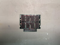 | |
| Posted by: jmacz on 2026-06-16 17:36:30 Been playing with this a bit... I have three different CPU cards all of which have had CPU transplants.
I need to find some more time to muck around some more but the next thing I could try is adding a fan. How? Well you have two compartments next to the CPU card. With a SCSI emulator, you might have enough room to add a small fan that blows horizontally into the CPU compartment (might need to create a hole) or you could sacrifice the floppy drive on the other side. At the cost of draining the battery a bit more. | |
Posted by: croissantking on 2026-06-16 18:13:04Been playing with this a bit... I have three different CPU cards all of which have had CPU transplants. At 40MHz I can’t get any of my CPU cards (I’ve tried about 3) to pass more than 2 runs of MacBench’s graphics test without dying, and that’s only with 36MB RAM. With 20MB RAM there’s no problem, so the memory controller evidently has to work harder with more banks activated. I absolutely did not expect you to run stable at 40MHz with 48MB RAM, in fact I’m impressed you even tried! I can see three possible ways to solve this. One, find a way to add an extra wait state for the DRAM - this would be the most ideal. Two, bump the voltage to the memory controller and/or DRAM slightly. Three, add cooling (as you suggested). If you do go the cooling route, bear in mind you will have to create intake and outtake vents - you can’t just blow air on the cpu in a closed box. Perhaps you could draw air in through the floppy opening and blow it out the opposite side, through a new hole that you cut next to the hard drive bay. | |
Posted by: jmacz on 2026-06-16 18:28:19If you do go the cooling route, bear in mind you will have to create intake and outtake vents - you can’t just blow air on the cpu in a closed box. Perhaps you could draw air in through the floppy opening and blow it out the opposite side, through a new hole that you cut next to the hard drive bay. Yeah, was staring at my bench 540c and was thinking about how to save the floppy but with it in place, I don't think it will intake/exhaust correctly. I could do three holes (left exterior next to the hard disk bay and both sides of the CPU bay) and then out the floppy port. But before that, I can just add a heat sink and try with a normal fan on top to see if it even helps first. The other thought was to blow air in from an empty battery compartment and exhaust out with a new hole in the rear but I would need to 3d print some ducting to direct the air. | |
Posted by: croissantking on 2026-06-16 18:37:04Yeah, was staring at my bench 540c and was thinking about how to save the floppy but with it in place, I don't think it will intake/exhaust correctly. I could do three holes (left exterior next to the hard disk bay and both sides of the CPU bay) and then out the floppy port. But before that, I can just add a heat sink and try with a normal fan on top to see if it even helps first. Makes sense to see if cooling helps first. But is it the 040 that needs active cooling, or the memory controller? (Maybe both…) It would be good to try sticking a heatsink on the latter but with it facing down against the logic board there really isn’t an easy way to do that. | |
Posted by: jmacz on 2026-06-16 19:44:54Makes sense to see if cooling helps first. But is it the 040 that needs active cooling, or the memory controller? (Maybe both…) It would be good to try sticking a heatsink on the latter but with it facing down against the logic board there really isn’t an easy way to do that. Yeah, that seems difficult. | |
| Posted by: zigzagjoe on 2026-06-17 06:44:02 IME the bus drivers are the first things that get weird on 040s in regards to temperatures. So the system getting crashy with a bit of additional bus loading from more DRAM doesn't surprise me. Putting directed airflow on the CPU with a heatsink (of any kind) temporarily sat on top would be a good test to verify it's the CPU getting hot. If you have any ability to measure temperature, anything above ~ 50 deg C on the CPU case is getting too hot as the die will be hotter still. We've got some info from motorola on FPU vs LC chips showing that FPU costs you about a watt of power. That applies at all times; these chips don't do idling. Per specs, with that and the clock increase you've increased power dissipation by 50% (3w -> 4.5w). That said, in absolute terms, that really isn't all that much heat. There's not really a need for a quantum increase in cooling capacity, just a nudge. @croissantking tells me there's a steel heat spreader block without TIM; a good first step would be adding some kind of TIM, and a second step would be to replace that steel with copper. If it really came down to you could stuff a small squirrel cage blower fan in there (space permitting) and not worry about exhaust/intake too much as the goal is mainly to get heat away from the CPU die, even as ambient temp increases, CPU temps will still ultimately work out lower. 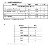 I did a little more measurement of the 040 QFPs here. | |
| 1 |