68kMLA Classic Interface
This is a version of the 68kMLA forums for viewing on your favorite old mac. Visitors on modern platforms may prefer the main site.
| Click here to select a new forum. | |
| Macintosh II Motherboard Revisions | |
| Posted by: David Cook on 2025-06-27 14:55:52 There are at least four production versions of the Macintosh II logic board that I'm aware of. I'd be interested if anyone has a board other than the ones listed below. Macintosh II 820-0163-02 I don't have this board. The next set of images is from Bruce at Branchus Creations. This is the earliest board I'm currently aware of. 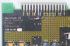 It has a bodge pull-up resistor (+5V->100 kilohm->RxD+ modem serial receive pin) presumably to prevent the board from accidentally entering burn-in-diagnostic mode. It has axial tantalum and electrolytic capacitors. It does not have the surface mount electrolytic capacitors that plague the most common Macintosh II board. 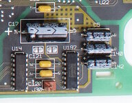 The capacitors all seem to be populated, including those beside the Apple Sound Chip (U72 below). 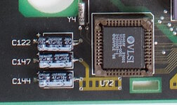 Macintosh II 820-0163-03 I have two of these boards. Comparing the photo of the -02 board to my -03 boards, the boards seem identical. I assume either something on the back or something else I haven't spotted is different. The -03 board also has the resistor bodge at top. Why wasn't this fixed between the -02 and -03 board? 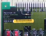 Similar to the -02 board, this has a set of PAL chips for NuBus control. The later Macintosh II board uses a single NuBus chip. 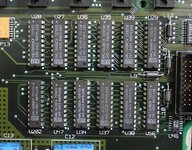 Like the -02 board, the -03 board does not have surface mount electrolytic capacitors. However, unlike the -02, Apple doesn't seem to be consistently populating them all. For example, C11 and C13 are missing in the image below. 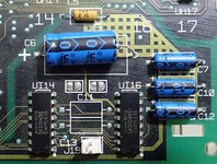 And all of the capacitors beside the Apple Sound Chip are missing on one of my -03 boards. They are all populated on the other -03 board. 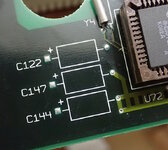 There is a factory bodge on the back of the board. Someone forgot to run ground traces! 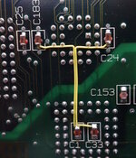 Interestingly, Apple was still shipping the defective 342-0105A to 342-0108A ROMs as recently as the the -03 board revision. These ROMs are apparently quite rare, as Apple recalled them due to a bug in accessing more than 1 MB of NuBus space. This would have constrained 24-bit video cards, for example. The 342-105-B ROMs fix this bug, and the 342-0639-A/B/C ROMs offer FDHD floppy support. So, the A ROMs were largely replaced. 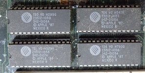 On the -03 revision motherboard, the battery footprint does NOT include the ability to add standard commercial battery holders directly on the board (without a carrier). That is, there are only two holes for each battery. 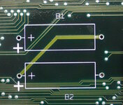 For comparison, this image from a later revision shows two extra holes for each battery holder, along with a big hole for the battery-holder-polarity-alignment peg. 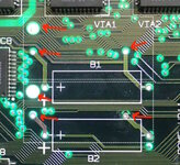 Macintosh II 820-0163-B As of at least this board revision, Apple fixed the resistor bodge, the underside capacitor ground wire bodge, and added the holes for battery holders (which they unfortunately didn't use). Surprisingly, most components got renumbered. For example, C136 is now C3. U31 is now UB1. This is really strange, as most of the components are still the same -- just numbered differently. This makes repairs more difficult, because when someone says "check C3" I can't be sure we're talking about the same C3 unless I know your board revision. 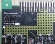 (post continues) | |
| Posted by: David Cook on 2025-06-27 14:57:39 (continued from previous) Macintosh II 820-0228-A Don't be confused by the 'A' on the end. Notice the part number has increased from 0163 to 0228. This 'A' board is newer than the 'B' board pictured above. This 'A' board is the most common. Aside: The words "Macintosh II" have moved from the upper-left corner to a larger font towards the bottom-left of the board. This, and the NuBus chip make a 0228-A board easy to spot on eBay. 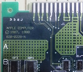 Unfortunately, Apple switched to surface-mount electrolytic capacitors in many places, thus beginning a long line of motherboards that self-destruct over time. The power switch and power circuit (UB1 and UB2) are the most common failure points due to capacitor leakage -- but are repairable. Frustratingly, Apple additionally renumbered some components on this board. The Bomarc schematic refers to this board revision. It does not match earlier boards. This board includes a NuBus chip instead of PALs. 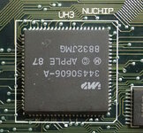 (post continues) | |
| Posted by: David Cook on 2025-06-27 14:59:05 (continued from previous) Power Off Oddity After pressing the rear power button on any of the Macintosh II line (II, IIx, IIcx, IIci, IIfx, etc), the computer turns on. Quick -- what happens if you then immediately hold down the rear power button? It turns off, right? Well, surprise surprise, it didn't originally work that way. Apple hadn't yet perfected soft-power. On at least the Macintosh II 820-0163-B and earlier boards, holding down the power button early in the power-up sequence does not power off the Macintosh. This is because the power "off" portion of the button originally connected to input pin 10 of the GLU chip, and the GLU chip has to be set to perform a power off. If there is a defect on the board, such that the computer doesn't make it far enough in the power-up initiatilization, then holding the power button does nothing. It will not turn off. You need to pull the plug. This is not caused by a corroded trace. It is a design limitation. If the computer makes it far enough to initialize the GLU, but hasn't made it to the screen with the cursor/disk, then holding the power button will cause a power cycle (restart), instead of turning off. This is because the GLU can now read the power button and activate the power-off circuit, but then the power-on circuit sees the button is held down and will power up the computer! If the computer makes it to the cursor/disk screen, then something more intelligent occurs. The GLU or ROM code seems to wait for the button to be released and issue a power off that actually takes effect. This is clumsy. On at least Macintosh II 820-0228-A revision, Apple made two important changes: They added a power-on delay circuit and they directly wire the power-off button to the power-off circuit (bypassing the GLU chip). Here's an older board: 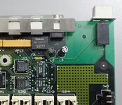 Here's the newer board. Notice traces coming from the power switch. One of those traces connects to C3. 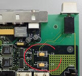 On the Bomarc schematic (see below), C3 provides a power-on delay. When the computer has been powered off long enough, C3 will have drained through R9 (which is essentially grounded because power is off) and reaches a low voltage. Pressing the power button drains C6 (which had a default high signal via the battery through R18) which turns on the machine. Powering up causes C3 to fill up to 5V through the power supply through R9. Great. The machine is powered up. When the user presses the power button to turn off the computer, C3 is now high (not low) because the computer has been powered on. Until the machine powers off and C3 has time to drain through R9, C3 cannot provide the low signal to turn the computer back on. Thus, instead of the computer repeatedly restarting immediately, it turns off until enough time has passed to drain C3 and start the power up cycle again. R9/C3 is a delay circuit. 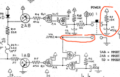 In the above schematic, I've also circled a line coming from the other half of the power button. The power button is now directly connected to the power off circuitry. It no longer has to be processed by the GLU chip (or ROM code) to power off the machine. No more pulling the plug. Below, we note that pin 10 of the GLU is no longer used and is simply pulled high through the resistor pack. I imagine you could add a power off switch here and it would still work. Not sure why you would do so. 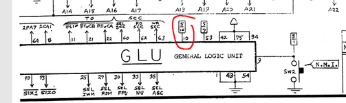 If you have any Macintosh II boards other than the four discussed in this post, I'd be interested in hearing about it. - David | |
| Posted by: nathall on 2025-06-27 18:46:07 I just wanted to say, I always really enjoy reading your extensive breakdowns. | |
Posted by: David Cook on 2025-06-27 21:16:29I just wanted to say, I always really enjoy reading your extensive breakdowns. Thank you. To me, it is like solving an old puzzle and sharing the solution with friends. | |
Posted by: ObeyDaleks on 2025-06-28 06:18:28Power Off Oddity This is very interesting. I actually wondered about this when turning my early Mac II on, then immediately off. My IIx and IIfx will reliably turn off after a delay, but Mac II would just power-cycle instead. I actually thought I might have some power circuit issue. | |
| Posted by: ObeyDaleks on 2025-06-28 06:22:07 . | |
Posted by: David Cook on 2025-06-28 08:52:59I actually thought I might have some power circuit issue. That's exactly what I thought when I was recapping/cleaning one of those older revisions. When I couldn't tone out the power-off side of the switch per the schematic, I ended up following the trace using the 'brush' method. That's where you connect one side of the multimeter to a metal brush and make sweeping passes over the entire board. When you hear the tone, you remove the brush and poke each via/pin nearby to find the specific connection. Here's a picture of my little post it note in each place I found a connection. 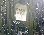 | |
| Posted by: dougg3 on 2025-06-28 09:37:33 Really nice analysis as usual, David! I had no idea that the power off portion of the circuit had been tweaked in different revisions of the II. That's really good to know. I know that my post from 10 years ago about the power circuit is often referenced by people, so I added a note with a link to this thread. Thank you for sharing this info with the world! | |
Posted by: David Cook on 2025-06-28 13:10:15e power circuit is often referenced by people Ah yes! I, too, have referenced that power circuit. I'm glad that I have been able to contribute a little something back to it. | |
| Posted by: David Cook on 2025-10-06 11:54:28 I found another variant. This is 820-0163 A (circa late 1987 early 1988). It has the part renumbering like it's successor, 820-0163 B. 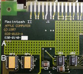 It also has the holes for battery holders, like its successor. However, the polarity peg holes are non-plated on A, but plated on B. 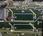 Most significantly, the A board has the bodge wires for C151/C152. They fixed this in the B board and extended the inner plane (the dark area). 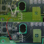 | |
| Posted by: David Cook on 2025-10-06 12:00:40 Another oddity on this particular Macintosh II are three ground contact fingers atop the power supply. I haven't seen this on any other Macintosh II power supply. The contacts do not appear on other power supplies with the same part number: CR-45 (68-1073-5) 699-0389 REV E6, M23. Yet, they seem like original OEM. 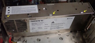 They make contact with upper RF shield on the lid of the Macintosh II. I assume this improves RF suppression? 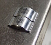 | |
| 1 |