68kMLA Classic Interface
This is a version of the 68kMLA forums for viewing on your favorite old mac. Visitors on modern platforms may prefer the main site.
| Click here to select a new forum. | |
| Quicktake 100 and 150 Recapping Guide | |
| Posted by: croissantking on 2025-04-20 06:13:42 Here’s a step-by-step guide explaining how to disassemble a QuickTake 100. It should be identical for a QT150. It is difficult to do, but hopefully this guide will help. Make sure you keep your screws organised in a jewelery box or something similar with compartments, as there are a lot of them. Spoiler content hidden. Here is a link to a Mouser project. To begin, remove a 5.8mm screw next to the tripod mount.  Remove a long 28mm screw holding the top and bottom housings together. 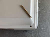 Remove a 5.3mm screw from inside the battery compartment. 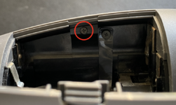 Remove a 5.3mm screw securing the fascia, next to the eye cup. 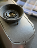 The rear fascia can be lifted away now. 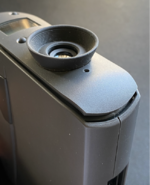 First, lift away the acrylic lens covering the LCD and store it somewhere safely. Notice a clip which you can gently lever up, enabling you to lift away the top half of the outer casing. 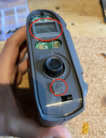 Now you will see the top PCB EP02A-4. Here you must: - Remove 3x 4mm black screws with large heads - Remove 1x 4.8mm silver screw - Disconnect 2x ribbon cables and 1x JST connector. 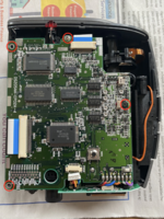 Desolder 8x coloured wires from the corner of the PCB: 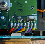 Also desolder a black ground wire on another corner: 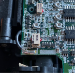 The board is ready to be lifted away and put aside for recapping. On the top side there are 2x electrolytic capacitors that need replacing. They are in an unusual form factor which makes recapping more complex. 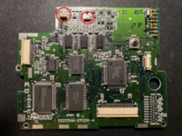 Underneath are 7x electrolytic capacitors that need replacing. 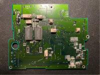 As you see they are just a regular electrolytic cap encased in plastic. These aren’t available in this form factor anymore. 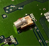 To remove them, snip the leads near the pads with a pair of side cutters, then use hot air (but turned down low, to 100˚C) to soften the glue at which point the plastic casing can be pried up with a flat blade. 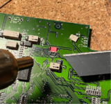 For reference this is how I’m replacing them – with regular radial capacitors with their legs bent over. 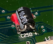 Here’s this particular board done. 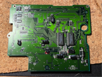 One of the very smallest caps is a tantalum as I couldn’t find a small enough radial cap, it fits nicely across the pads. 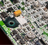 Back to the main housing, optionally remove the CCD flat flex cable, and the red LED lens (be careful as it’s easily lost), and store them safely. 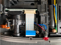 The LED sits inside a little black housing – take note of how it’s fitted to the casing for reassembly. 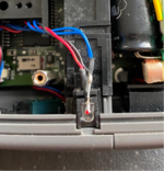 Also note these two moving points of contact for the door covering the serial and DC in ports, these should be cleaned and regreased. 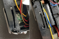 The battery door now needs to be unhooked from the two plastic nubs holding it in. With a pointy tool, press into the centre of one of the hinges to unhook it. 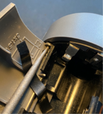 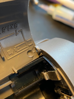 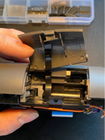 Next remove 2x 6.4mm screws – 1 from the inside edge of the housing by the viewfinder, and another by the battery bay. 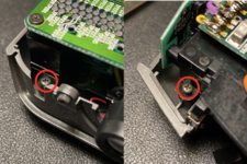 As you lift out the inner frame from the lower casing, be sure to disconnect this small cable for the lens cover sensor. 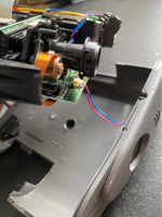 Orient the camera so that the LCD is facing you. Remove 2x 4mm screws from the PCB, but don’t lift it out yet. 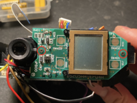 Disconnect this little cable from the JST header. 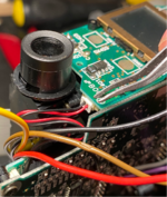 Now lift this small PCB away from a larger PCB, it is held in by a single connector. 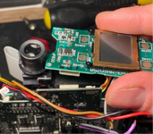 With the LCD board lifted out, note how the coloured cables are routed for when you come to reassemble. 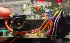 There’s a supercapacitor on the back of the LCD board that needs swapping out. 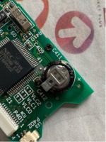 Turn your attention to another large PCB, EP03A-4. Again there are cables, screws and wires that need removing. – Remove 3x 4mm screws with large heads – Remove 1x 4.8mm screw with a silver head. 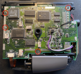 Note the silver headed 4.8mm screw attaches to a long post on the other side. 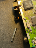 Remove this small flat ribbon connector labelled ‘shutter’. 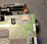 Coming back to the large PCB, desolder just the black wire. 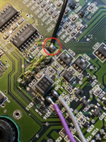 You are ready to lift the EP03A-4 PCB out. Take note of the routing of the flat flex cable through the main housing for when you come to reassemble. 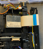 The PCB is held in by a couple of small connectors, so gently lever it out on the same side. 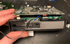 Here is a view of the board partially lifted out, which might be useful during reassembly. 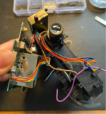 Now the board is free, disconnect flex cable labelled ‘process’ and 2x small harnesses with JST connectors. 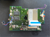 Here’s the board view, top side, featuring 3x odd shaped capacitors. Also, there are many more hiding inside that metal box. 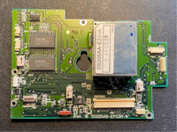 Here's the underside of the board with 5x electrolytics. Pay special attention here to mounting the new caps flush as clearance against the lower casing is limited. 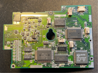 The metal box now needs removing from the PCB: – Underneath: 10x pins to desolder – On top: 2x large solder joints securing the metal case to the ground plane. Once you have done this the box should lift away. It will definitely need some gentle teasing and patience. 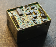 You then need to desolder the small PCB EZ01A from the metal case on either side, after which it can be pried out. The board comprises tightly packed components, with a mixture of through hole and SMD capacitors. 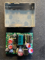 Here’s mine after desoldering – some caps had leaked – and after recapping. The purple caps are polymers, they can’t leak but I decided to replace them anyway since ESR and capacitance can drift over time. 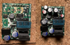 Back to the camera now, this is the flash PCB that we need to get access to next. 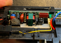 Remove these two 5.7mm screws holding a detachable section of the frame. 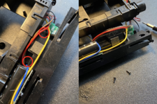 Disconnect this small cable, with yellow and black wires. 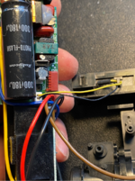 Now you can separate this part of the frame. 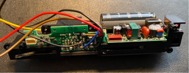 Desolder this blue wire. 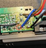 Remove 2x 4mm screws holding the flash PCB in place. 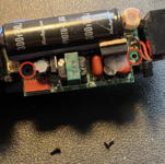 Remove a small screw holding a ring terminal to the flash bulb housing. 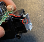 Lift out the flash bulb housing 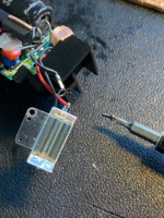 To be continued... | |
| Posted by: croissantking on 2025-04-20 06:26:53 There is just one small cap to replace. For the large 300V cap I couldn’t find a suitable replacement so I had to leave it. I suppose ‘photo-flash’ caps aren’t that popular anymore. 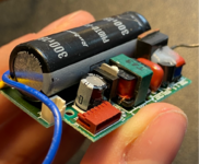 All boards taken out. You’re done – hope you organised all the bits and pieces nicely. Go ahead and recap everything, then follow this guide in reverse order to reassemble. 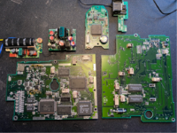 Bonus Material I just wanted to quickly show how I fixed a couple of common issues with this camera. Many of them have been stored for decades with leaky batteries which means you can't run them anymore without an AC adapter. Here's how mine looked before: 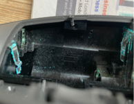 And after cleanup and repair. Some of the contacts were ready to drop off after scraping off the corrosion, so I reinforced them with solder. 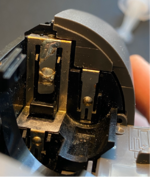 I had another issue that was driving me insane. Basically, there was something wrong with the serial port, and I could only get a connection to a Macintosh when I pushed upwards on the cable. The serial port itself looked fine and further investigation revealed dry solder joints on a 'COM' connector on EP03A-4. This is where the serial port board plugs into. 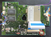 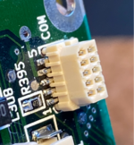 So if you are having connectivity issues, be sure to inspect this connector. I reflowed both the one shown and the mating female connector on the serial port board. | |
| Posted by: Durosity on 2025-04-20 07:01:47 Amazing guide, although I did accidentally read the spoiler and was really disappointed to know the capacitor values ahead of time. Talk about an anti-climax. | |
| Posted by: stepleton on 2025-04-20 14:58:08 Fantastic guide; I don't have one of these cameras (although I used one back in the day) and it was still interesting to see the way it went together thanks to the fine photography. Strange packaging for electrolytics; I've never seen that before! | |
| Posted by: jmacz on 2025-04-20 21:40:35 Nice write up! Can't believe all of that fit inside! | |
| Posted by: MindWalker on 2025-04-21 05:05:20 Brilliant work! Although I must say I am not looking forward to doing all that work on my camera! Does any of the image sensor deconding rely on analog circuitry, ie. the caps? Ie. did the degraded cap have a visible effect in the pictures themselves?? 🤓 One additional issue that I had was that the main power switch (the sliding lens cover) was not always making good contact giving me a low-battery -condition on good batteries. I opened the case and was able to carefully put some contact cleaner into the switch and that cured it. | |
| Posted by: stynx on 2025-04-21 06:50:47 Fantastic! I will have to redo my previous recap since i have definitely overlooked some of the caps you have shown. Spoiler content hidden. | |
Posted by: croissantking on 2025-04-21 08:28:20A (printable) PDF would be the cherry on the cake since i don't have easily accessible internet at my place for soldering (in the basement). I have saved this guide on my drive but it has over 50 pages as a result of bad formatting of the layout for printing. I will do this, it will be easy as I created the writeup in Word and then copied and pasted everything into a forum post. I think it’s a good idea anyway; in case anything ever happens to the forums there would be a backup. I don’t think I’d be keen to recreate this guide as it was loads of work! | |
| Posted by: 4seasonphoto on 2025-05-11 11:01:43 Good work! Some oddly-shaped photo flash capacitors are still available, but they're often special-order items from Mouser or Digikey, with minimum orders being 1000 pieces. Other sources include AliExpress (can't guarantee that name-brand parts are genuine though), and they can also sometimes be salvaged from disposable film cameras. | |
Posted by: croissantking on 2025-05-11 14:24:48A (printable) PDF would be the cherry on the cake since i don't have easily accessible internet at my place for soldering (in the basement). I have saved this guide on my drive but it has over 50 pages as a result of bad formatting of the layout for printing. Here's that PDF you wanted, @stynx – hope it's useful. | |
Posted by: stynx on 2025-05-11 15:03:08Here's that PDF you wanted, @stynx – hope it's useful.Thanks a lot! | |
Posted by: croissantking on 2025-05-11 15:17:46Thanks a lot!You're welcome, good luck 😊 | |
| Posted by: zigzagjoe on 2025-06-07 10:51:53 Thanks for this guide! Fantastically done, parts list worked perfectly. I found I didn't need to fold the leads under the caps, thankfully. Mind the clips on the housing when splitting the case and removing the chassis from the case. Replacement for FU291: Littelfuse 04513.15MRL  | |
Posted by: croissantking on 2025-06-07 10:55:13Thanks for this guide! Fantastically done, parts list worked perfectly. I found I didn't need to fold the leads under the caps, thankfully. Mind the clips on the housing when splitting the case and removing the chassis from the case.Excellent - glad to hear! What was your method for caps? | |
Posted by: zigzagjoe on 2025-06-07 11:17:00Excellent - glad to hear!I was able to get away with just folding them flat facing away from the cap. The modern caps were all shorter so they stayed within the silkscreen cap footprint on the board. I also found after clipping the cap leads I was able to just give a slight twist to break the glue, no heat needed. I didn't take a picture of the finished caps unfortunately. | |
Posted by: croissantking on 2025-06-07 11:19:20I was able to get away with just folding them flat facing away from the cap. The modern caps were all shorter so they stayed within the silkscreen cap footprint on the board.Cool. I changed up the BOM after I did the recap job with smaller parts for all the 6v 47uF ones, so that probably helped. | |
Posted by: zigzagjoe on 2025-06-07 11:31:44Cool. I changed up the BOM after I did the recap job with smaller parts for all the 6v 47uF ones, so that probably helped.Yep, they worked just fine fittiment wise. The power module had all TH caps leaking including the purple one, oddly enough the SMDs were fine. | |
| Posted by: DJ68K on 2025-06-12 19:17:20 These caps look like the same type of capacitor that infests & is wrecking every Sega Game Gear ever made. I guess I have a weekend ahead of me with my QuickTake. Before and after pics of a Game Gear attached. | |
| Posted by: MOS8_030 on 2025-06-12 21:34:21 Very impressive guide! Makes me glad I sold my QT while it still worked.. | |
| Posted by: croissantking on 2025-06-20 07:21:55 There seems to be a common belief that the QT150 is identical to the QT100 in regards to hardware, just with newer firmware. Having now had a QT150 apart, I can confirm that one of the boards was redesigned. 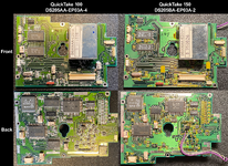 | |
| 1 |