68kMLA Classic Interface
This is a version of the 68kMLA forums for viewing on your favorite old mac. Visitors on modern platforms may prefer the main site.
| Click here to select a new forum. | |
| Mac SE/30 suddenly strange screen. [see photo] Startup Chime good. | |
| Posted by: isokinetic on 2024-12-15 04:10:26 I‘ve recently acquired a recapped SE/30 that was working. I had it running three hours when suddenly the screen did not longer work properly. I had to restart using programmer switch. It does chime but the screen only shows a strange image. 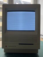 I swapped the analog board with a working 1/40 (both used C type) and used another ROM from a SE/30 but to no avail: Chime but same screen. I swapped the analog board with a working 1/40 (both used C type) and used another ROM from a SE/30 but to no avail: Chime but same screen.Can you point me what to do next please? Kind regards! | |
| Posted by: cheesestraws on 2024-12-15 06:23:25 When you swapped out the analogue board did you also swap out the cable between the AB and the LB? If not, try that | |
| Posted by: djc6 on 2024-12-15 07:57:29 I had a similar experience recently on my first classic mac (an SE/30). I recapped, it worked for a while, then a black screen. Turns out chip UG8 went bad - I think the leaking capacitor electrolyte got to it. I was able to figure it out by purchasing a cheap oscilloscope from Aliexpress and an ATX power supply extension cable, so I could run the machine with the logic board outside the case. I had to learn about reading schematics and using an oscilloscope, and surface mount desoldering/soldering - but in the end I was able to narrow down the one bad chip and replace it, and I have a working machine now! Oscilloscope I bought - Zoyi ZT-703S with two probes: https://www.aliexpress.us/item/3256...st_main.5.2ab91802zciZ35&gatewayAdapt=glo2usa There are other inexpensive, handheld oscilloscopes from Hantek and OWON. I picked this one because many retrocomputing youtubers say its decent for a first oscilloscope, the company seems to offer firmware upgrades for it, and its easy to take screenshots to post on forums (you use usb cable to transfer them to PC). It also has one of the biggest if not the biggest LCD of various handheld scopes. ATX board extension cable I bought: https://www.amazon.com/gp/product/B09N9BZRD9/ref=ppx_yo_dt_b_search_asin_title?ie=UTF8&psc=1 This cable lets you extend the connector at J12 to the analog board, so you can position the logic board outside the case. Here are threads on my recent adventure: SE/30 went from working to no video (does chime on startup)I have an SE/30 that I recapped a couple weeks ago. Its worked fine and i've probably put 20-30 hours on it since recapping playing tetris and exploring HD images via my BlueSCSI v2. Its never once crashed or behaved strangely. Earlier today I was looking at some old documents in ClarisWorks...
Safest technique for removing SOIC chips on SE/30 like UD8, UE8, UF8, etc.I am going to attempt replacing UG8 on my SE/30. What is the best way to remove SOIC chips like these? I've done some research and Chip Quick (ChipQuick?) SMD removal solder is a possible way, though the "mess" afterwards is a little concerning - looks like you need to use this stuff...
To my untrained eye that has only ever worked on one SE/30 and with minimal retro repair experience, it looks like you have VSYNC and HSYNC (vertical and horizontal sync) but you are missing the "Video Out" signal. I would be curious if an oscilloscope shows working VSYNC (pin 14 on UG6) and working HSYNC (pin 13 on UG7) but MISSING VIDOUT signal (pin 13 on UG6). If you are missing VIDOUT then I would suspect chip UF8 the binary counter surface mount chip is bad, which seems like a common chip to fail due to its proximity next to leaking capacitor C7. Depending on the revision SE/30 motherboard you have, you may have to modify the ATX extension cable a bit as shown in this video: Video shows a 24-pin atx extension which is really wide, I purchased a 20-pin atx extension since its less wide - it fits without modification on my later revision SE/30 where the CPU is not socketed but instead soldered to the board. | |
| Posted by: bibilit on 2024-12-15 10:48:00 Your issue is related to UE8, part number is 74LS166 (don’t use the HC one) near a leaky capacitor, common issue goes bad frequently. | |
| Posted by: isokinetic on 2024-12-15 12:35:53 Many thanks for your many and kind replies. The legs/joints on UE8 look a tiny bit corroded, but the label on the part is gone (burnt?). [see image] This built my resolve to go a little more serious with this hobby. I don't own an soldering iron, isolating transformer, or oscilloscope. all of which I will buy now. thanks for your suggestions. 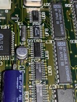 | |
| Posted by: bibilit on 2024-12-17 23:57:08 yes this is the one, UE8 (74LS166D) 74LS166D - RetroTechReparationer, reservdelar och komponenter till retrodatorer så som Commodore 64, Commodore 128, Amiga, Atari, Spectrum, Flipperspel, Bally, Sega, Zaccaria, Data East, Gottleib, Wiliams. Repairs, spare parts and components for retro computers such as Commodore 64, Commodore 128, Amiga, Atari...
You will need a soldering iron at least, but probably easier with hot air. | |
| Posted by: finkmac on 2024-12-18 05:41:54 if it's gonna be replaced, might as well just cut the leggs off the old one with some flush cutters | |
| Posted by: imactheknife on 2024-12-23 16:13:40 A friends board looks just like that and we replaced ue8 and no change. So not sure what next. Unfortunately this board has some rotten vias. | |
| Posted by: isokinetic on 2025-07-15 05:52:45 Hello! So I got a bunch of other stuff off my desk and thanks to your suggestions bought a soldering station etc. Removing the UE8 proved more difficult. Eventually frustrated, I cut its legs. When removing the legs from the pads I damaged two pads (see photo). How would you go about fixing this? Is this fiaxable? Thanks again for all your suggestions so far: oscilloscope will arrive in a couple of days… This forum is so helpful (someone here had the same screen as me, solved with replacing UE8, so I am hopeful). Looking at the photo on the larger screen I see that I might have caused more damage. Do you see other problems? 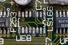 | |
Posted by: nyef on 2025-07-15 09:38:48Hello! So I got a bunch of other stuff off my desk and thanks to your suggestions bought a soldering station etc. Removing the UE8 proved more difficult. Eventually frustrated, I cut its legs. When removing the legs from the pads I damaged two pads (see photo). How would you go about fixing this? Is this fiaxable?Conductive epoxy, and a bit of copper tape to replace the outright missing pads. Specifically, epoxy down the partly lifted pads, and epoxy pad-sized bits of copper tape (adhesive side up, since the adhesive on copper tape degrades trivially with heat or IPA) to replace missing pads. Once the copper tape is secured down you remove the backing and clean up the normal adhesive, tin it, and solder in your new chip. Then bridge continuity gaps with wire (30 AWG or finer). | |
| Posted by: ObeyDaleks on 2025-07-15 12:29:31 Personally I would just solder the IC down and then run a wire from the via to the leg. Before all that, I would clean up the pads and scrape the traces to ensure you have continuity (pad 2 trace looks broken, for example). Lifted pads don’t matter as long as you have a few good pads to hold the chip down. | |
| Posted by: nyef on 2025-07-15 13:17:30 Ah, yes. Sorry, I was focusing more on the pads themselves (which I found to be necessary when I tore both pads to a leaked surface electrolytic). There's probably enough integrity on the remaining pads that you could just solder in a new chip and then wire directly to the chip pins. In any case, the actually problematic scenario is if a pad with a trace leading to a via under the chip needs repair, like with pin 7 in your case (it looks fine to me, but I'd double-check continuity with a meter anyway). And, of course, it also depends on how much you want to attend to the cosmetic aspect of things. | |
| Posted by: isokinetic on 2025-07-26 09:30:03 Hello! Thanks again for all your suggestions. I bought the oscilloscope and found that all traces were intact. I soldered a pad to the via (no glue, just the pad and lead solder). I then replaced UE8 per your suggestions. – It boots to 7.5.3 and I'm as happy as can be. Many thanks. That was a lot of fun. Thank you! | |
| 1 |