68kMLA Classic Interface
This is a version of the 68kMLA forums for viewing on your favorite old mac. Visitors on modern platforms may prefer the main site.
| Click here to select a new forum. | |
| Mac Plus that went on fine (only the analog board) | |
| Posted by: ironborn65 on 2024-11-26 15:57:53 this is the beginning of the repaying of the Mac Plus that went partially on fire Classic, LCIII, Plus, SI for for freeI was handed these Macs for free The Plus went on fire ... what would you do with it??
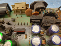   how splendid! 😀 it's better not to be frugal and replace all the darkened resistors, diodes and capacitors. What about inductances... can I measure the H? Or simply replace them all with no mercy? They are "only" for filtering purposed.. any advice? | |
| Posted by: LaPorta on 2024-11-26 17:03:47 GEEZ....how did that happen?? | |
Posted by: Callan on 2024-11-26 17:06:30GEEZ....how did that happen?? Big Bang Theory... 😁 | |
Posted by: ironborn65 on 2024-11-26 23:24:24GEEZ....how did that happen??I don't know, I was given the Plus for free in this condition. | |
| Posted by: joshc on 2024-11-27 02:22:59 Looks like things got a bit spicy there! | |
| Posted by: cheesestraws on 2024-11-27 02:34:05 As a note, you'll want to clean the surface of the board *extremely* carefully (or get one of the new replica boards) - the burnt material is much more conductive than the unburnt material, and there are mains voltages sloshing about down there. | |
| Posted by: ironborn65 on 2024-11-27 15:17:59 @cheesestraws Ah ahn ... thanks mate. I was underestimating this aspect. I found this project for the reloaded board GitHub - daanvdl/Macintosh-Analogboard: Macintosh 128K/512K/Plus Analogboard recreation (820-0107-D)Macintosh 128K/512K/Plus Analogboard recreation (820-0107-D) - daanvdl/Macintosh-Analogboard
 github.com
any other source to recommend? BTW: the fire started from the RIFA capacitor! | |
Posted by: cheesestraws on 2024-11-27 15:30:34I found this project for the reloaded board yes, @daanvdl's was the one I was thinking about. Do you have the schematics for the 240V version of the board, and do you have the analogue board guide PDF? | |
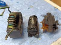
| Posted by: ironborn65 on 2024-11-27 15:59:47 I'm browsing for this info, I got the Apple one, but I'm looking for the BOM because the inductors L9 L10 are probably gone and also the transformer, LF1 LF2 It's unclear if the circuit of the reloaded and its BOM correspond to the original Apple board. I'd like to avoid the reloaded, | |
| Posted by: daanvdl on 2024-11-27 23:10:20 Hi Ironborn! Thats a toasty Plus! 😲 Yes, The BOM on my reloaded correspond to the original Apple board (rev 820-0107-D). The board is a 100% replication. If it is a 110V board some parts will differ. LF1 and LF2 are linefilters. Probably you will be able to find replacement parts. The footprint will be the most challenging 🙂 | |
| Posted by: ironborn65 on 2024-11-28 00:17:17 Thank you, @daanvdl, and thanks for the PCB recreation. Could you provide the specifications for the line filter? Would any line filter work? I have some non-functional switching power supplies, and I was thinking of measuring the inductance to ensure a proper fit. Is that the correct approach? How to measure the Henry? Also, what are the specifications for the L9 and L10 components? They are not shorted but appear to have been damaged by heat. By the way, is there a specific reason why the SW1 switch was not designed to be positioned higher, closer to the J5 connector? | |
Posted by: cheesestraws on 2024-11-28 01:15:19@cheesestraws Ah ahn ... thanks mate. I was underestimating this aspect. This is one of the big problems with electrical fires: burning things produces carbon, which acts like a resistor, which generates more heat, which burns more stuff, which makes more carbon, which generates more heat, and so on... I'm browsing for this info, I got the Apple one, but I'm looking for the BOM because the inductors L9 L10 are probably gone and also the transformer, LF1 LF2 This thread has the PSU schematics for the 240V version: https://68kmla.org/bb/index.php?threads/128-512-plus-240-v-psu-schematics.38953/ I did them initially then @michimartini made corrections. The PDF with details on how the bloody thing works is at https://vintageapple.org/gamba2/images/plus_analog.PDF - the theory of operation is the same for the 240V one but the schematics are slightly different because of the voltage difference. Could you provide the specifications for the line filter? Would any line filter work? Someone else may correct me here, but I believe that line filters are pretty interchangeable | |
| Posted by: daanvdl on 2024-11-29 04:09:32 I do measure around 1mH on both lines on the Plus filter (LF2) and around 15mH on both lines on LF1 with my LCR meter. Let us know if you can find new filters which will fit on the board! 🙂 I think it’s perfectly fine to deviate slightly in values if you find new suitable components. The original value might be tailored to meet stricter EMC (Electromagnetic Compatibility) requirements. | |
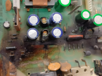
| Posted by: ironborn65 on 2024-12-08 10:04:29 some updates here the board was cleaned with the magic sponge LF2 despite the look, is not shorted and it tests 25mH not like the 15mH @daanvdl measured (thanks), but I'll keep it. LF1 looks terrible but there is no short and it tests 0,4mH and 0,5mH respectively L10 L6 test 0.2mH, I added a new shrinking tube. So in the end, I'm going to replace the capacitors, just in case, but the rest seems ok. But I have an issue with the N1 and N2 that looks like a small thermionic valve: one is fine the other has a pin compromised. They are in the picture attached. I don't see them in the schematics, what are those? How can I replace it? T | |
Posted by: cheesestraws on 2024-12-08 10:47:58I don't see them in the schematics, what are those? How can I replace it? T They are little neon light bulbs, believe it or not... | |
| Posted by: ironborn65 on 2024-12-08 10:50:48 wow what are those for?? | |
Posted by: cheesestraws on 2024-12-08 11:52:53what are those for?? overvoltage protection - if the voltage gets higher than the strike voltage of the bulb, the bulb starts to conduct quite enthusiastically and lights up and shorts everything out, protecting the components "behind" it. Quite a clever thing. 
Why have a small neon lamp in power supply input circuitry?A couple of times when taking apart older bits of electronics, I've seen a small neon lamp about the size of a fuse (but its definitely not a fuse) positioned near the power supply circuitry. What ...
 electronics.stackexchange.com
| |
| Posted by: ironborn65 on 2024-12-08 12:10:15 is there a replacement? or can I simply leave open the one that is broken o should I try to restore the broken pin? N .. does it stand for neon? 😀 😀 | |
| Posted by: daanvdl on 2024-12-09 00:30:12 NE1 and NE2 are NE-2H Neon bulbs. I believe 95VAC/135VDC rated. | |
| 1 |