68kMLA Classic Interface
This is a version of the 68kMLA forums for viewing on your favorite old mac. Visitors on modern platforms may prefer the main site.
| Click here to select a new forum. | |
| Overclock LC475/P475/Q605 without soldering or spicy-o-clock | |
| Posted by: Mustermann on 2024-07-18 12:21:36 As you may know, a LC475 lives with me. My current target is to operate that LC at 40Mhz, so I read some pages about ROM hacking and MEMC chip. From the schematic I know LC475/P475/Q605 are using programmable Gazelle clock generator chip. Based on schematic and that document I learned that Gazelle is connected to MEMCjr and pins can be controlled thru a register in MEMCjr (Clock Generator Register at $F98003C0) https://68kmla.org/bb/index.php?threads/wombat-650-800-board-overclocking-limitations.38538/page-11 #210 MEMCjr documentation is stating that Gazelle is in general a Sierra Semiconductor SC11412 dual programmable clock generator. So i read thru the SC11412 datasheet and found that it is loading a basic clock divider at startup based on the level of some inputs (those we are changing with moving resistors) But it can be programmed as well. As all of the relevant pins can be controlled by MEMCjr I tried to poke those pins to change setting of Gazelle. IT WORKS! I Poked these values: $F98003C0->$00 ; Tristate clock interface $F98003C0->$08 ; Set MEMCjr pins to output, set lines to b00 $F98003C0->$0C ; Reset Gazelle Register and load from input lines $F98003C0->$08 ; Return to normal (as I do not want to send data) $F98003C0->$00 ; Tristate clock interface Should ask Gazelle to load the config of both resistors connected to GND = 20Mhz Checked with Norton Sysinfo: 83% of before I Poked these values: $F98003C0->$02 ; Tristate clock interface $F98003C0->$0A ; Set MEMCjr pins to output, set lines to b10 $F98003C0->$0E ; Reset Gazelle Register and load from input lines $F98003C0->$0A ; Return to normal (as I do not want to send data) $F98003C0->$02 ; Tristate clock interface Should ask Gazelle to load the config first resistor connected to GND and second resistor connected to 5V = 33Mhz Checked with Norton Sysinfo: 137% of before Based of the documentation of SC11412 I assume that we can upload a customized configuration as well which is expected to choose one of a big bunch of clock frequencies. So neither soldering nor spicy-o-clock is needed to overclock LC475/P475/Q605 | |
| Posted by: Powerbase on 2024-07-18 12:26:30 Just in quick perusal at work, this is very neat. Excellent work. I'll let the more technical members scrutinize it, though, first before giving you a thousand internet points. | |
| Posted by: dalek on 2024-07-19 16:09:54 This is awesome! The way I read it you can dynamically change the clock speed with a few writes to memory? Is someone already looking to write an app to set the clock speed? Have you built a table of possible frequencies or is it just those two available without resistor/oscillator changes? | |
| Posted by: Arbee on 2024-07-19 16:35:56 Gazelle is programmable for a wide range of clocks - one is used for the monitor pixel clock in the Wombats, which are quite flexible there. | |
| Posted by: Mustermann on 2024-07-19 23:53:26 There are two ways to set up Gazelle in LC475: Chose one of four preset frequencies 20Mhz, 25Mhz, 33Mhz, 40Mhz that is what I described above. Programm internal divider and multiplier. So you can implement a lot of frequencies. I did not tried this yet. My assumption of the difference between Gazelle and SC11412 is that Apple mask programmed dividers for the preset frequencies and expanded the maximum input frequency a little bit. Frequency can be changed dynamicaly within a running system. My device started with 25Mhz and was changed to 20Mhz and 33 Mhz on the fly. Gestalt ID did not change. Be aware that poking Gazelle just change the clock frequency but none of the parameter used / needed for different frequencies. | |
| Posted by: Byrd on 2024-07-20 00:00:09 Amazing find - software overclocking was always there, before PCs! I’d love to see a little utility to poke the registers for Macs that can do this. | |
| Posted by: Mustermann on 2024-07-21 05:47:25 Setting CPU to any frequenz between 20 and 40Mhz work as well. I was able to verify with oszi. | |
| Posted by: cy384 on 2024-07-21 07:25:14 Great work! Do you plan to make an extension or something to do this on boot? It wouldn't be too hard to throw one together with retro68. | |
| Posted by: Mustermann on 2024-07-21 10:46:16 My programming skills are not sufficient for an extention yet. I am able to provide a prove of concept someone else need to support to write an extention. | |
| Posted by: Mustermann on 2024-07-21 12:44:58 Attached what I was able to implement until now. This program expect desired frequency in Mhz as input and is able to set all CPU frequencies from 20Mhz to 26Mhz and contain multipliers/dividers up to 42Mhz. It does not update any of the registers that are set on boot depending of the starting frequency. (Planed for V0.2) | |
| Posted by: Mustermann on 2024-07-22 13:23:43 V0.2 ready made. This version set all registers known from ROM and MEMCjr datasheet according to the tables in ROM and datasheet. All frequencies work for me. No crashes. Up from 38Mhz frequency does not increase any more. I assume something is not happy with those clock frequencies. First guess: MC88920 is the culprit. I will check at input and output with my scope later. | |
Posted by: Mustermann on 2024-07-22 13:35:12The way I read it you can dynamically change the clock speed with a few writes to memory?Frequency can be set dynamically while running the computer. There are all frequency settings from 20 to 42Mhz in one 1Mhz steps in the code file. Others frequencies are possible but based on my current experience there are limitations (not above 38Mhz in my case) | |
| Posted by: cheesestraws on 2024-07-23 02:17:51 For reproducibility: how are you validating that you're getting the frequency you think you're getting? | |
| Posted by: Bolle on 2024-07-23 02:28:55 It can't seem to get that to work either with the code you posted earlier. Speed just stays at 25MHz no matter the value I enter. | |
| Posted by: Bolle on 2024-07-23 02:58:21 Confirmed it does change all the other registers but doesn't touch the actual clock chip registers for some reason. It will always report b00000000 for the clock chip and always tells me it's going to set it to b00000000... 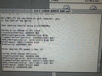 If I let it run again all the other "old values" match what it set before, so I believe that part does work just fine. It just isn't touching the clock chip for me for some reason. | |
| Posted by: Bolle on 2024-07-23 03:20:17 Nevermind, works on a different logicboard. What's interesting, the non-working board has a "343S0161" installed for the clock chip, the working one has a "343S1135" - what's on your board @Mustermann? All my boards have a MC88916 swapped in place, no problem to go up to 42MHz... we need faster settings now 😛 | |
Posted by: MacKilRoy on 2024-07-23 04:49:35For reproducibility: how are you validating that you're getting the frequency you think you're getting?The benchmarks posted seem to show the desired frequency is being obtained. | |
Posted by: cheesestraws on 2024-07-23 04:56:47The benchmarks posted seem to show the desired frequency is being obtained. ... yeah, I'm really not sure how I missed those screenshots. Sorry OP, I'm being a fool again :-D | |
| Posted by: MacKilRoy on 2024-07-23 05:06:32 I haven’t tried this yet @Mustermann but what would happen on a resistor swapped board where it is set to 33mhz on the board? | |
| Posted by: Powerbase on 2024-07-23 05:24:35 I take it the resistors are just setting the boot up frequency. This is neat but I wish I had a full 040 in mine, and not an LC. I've heard they don't overclock over 33MHz well. | |
| 1 > |