68kMLA Classic Interface
This is a version of the 68kMLA forums for viewing on your favorite old mac. Visitors on modern platforms may prefer the main site.
| Click here to select a new forum. | |
| LC475 / Quadra 605 Bad Caps Repair | |
| Posted by: squeak on 2024-04-03 08:38:08 Long time lurker; first post. Attempting to repair a bunch of bad vias on a LC475 / Quadra 605 motherboard and running into some problems because I don't have a good board to check against or any decent wiring diagrams... Board was owned by another person and they attempted a recap. I bought the board off of them after examining it and not seeing any major damage. After some repairs, board now has 'sad mac chimes', but no video. I am looking at 3 vias on the motherboard and am hoping someone with a good motherboard can help me figure out what they should connect to... All board damage is around U30 (343S0129-01) and confined close to C136/C137 and C149/C150 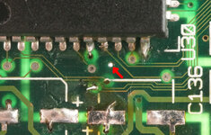 This particular via (marked by red arrow) goes through the back side of the board. I've drilled it out after testing it. There is some light around the via, but even the backside of the board doesn't have a connection to anything. 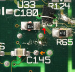 Looking at Bomarc's schematic for the color classic (supposedly similar design) I can see R40/R38 which match nicely to R64/R65 above. They beep (continuity) to Pin 22/23 of U30 and Pin 5/6 of U29 (341S0788) but I don't seem to have a connection to anything in the middle. Bomarc's schematics aren't the greatest, but it should apparently be connected to +5VDC. Orange arrow *appears* to be connected to the same internal plane, but I have -3.3VDC there (which seems odd, but may just be a red herring). Can someone confirm that +5VDC is the proper voltage between R64/R65? 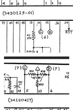 | |
| Posted by: squeak on 2024-04-03 08:51:36 2nd set of vias are here: I'm specifically worried about the cyan arrow, which doesn't beep top to bottom. (I've gouged it nicely with my probes) 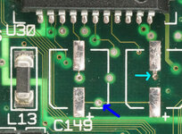 View attachment Via_2_Bottom.JPG C149 seems to match nicely with Bomarc's C5, which seems to indicate Blue arrow should be connected to ground... Unfortunately, there is no ground connection that I can find. it doesn't beep to ground and I don't see any connections to ground. (via has halo of light around it). The motherboard also indicates that this should be the positive side of the capacitor, not negative. (I'm not measuring a negative voltage on C149 -pad) The longer I looked the more confused I became... Cyan arrow drops down to unused pad on Q2 and doesn't seem to be connected to anything else... I don't have any idea where it would appear on the bomarc drawing (if it does). Question 1: Does blue arrow connect to ground? Question 2: Does cyan arrow have a connection I am missing somewhere? (and where does it go?) 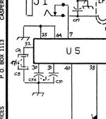 | |
| Posted by: codevonlux on 2024-04-04 06:35:42 This is schematics for LC475/605 that might be helpful for your debugging | |
| Posted by: squeak on 2024-04-04 16:56:34 @codevonlux 🙂 That is absolutely more than I could have hoped to get!! I definitely should be able to get this board working now! THANK YOU! | |
| Posted by: squeak on 2024-04-05 11:04:26 @codevonlux There is one very happy guy here! Board has been successfully repaired thanks to those awesome schematics! Currently running some stress tests on it, then need to do some final repairs once more caps arrive... Then maybe some shopping for upgrades... 😉 THANKS AGAIN! 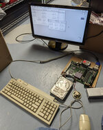 | |
| Posted by: squeak on 2024-04-05 11:12:47 ...and for everyone else looking at this and wondering about a conclusion: Red arrow need to have +5VDC connection to get proper data signalling to/from U30. There are a couple close points to connect to: C138 pad closest to edge of board, U33 Pin 4, C180. Take your pick. Orange arrow: Red herring Blue arrow: via is not connected to anything and is a test point only. Cyan arrow: Should be connected to ground/0vdc. R68 has a very convenient ground pad. | |
| 1 |