68kMLA Classic Interface
This is a version of the 68kMLA forums for viewing on your favorite old mac. Visitors on modern platforms may prefer the main site.
| Click here to select a new forum. | |
| Mac SE/30 Repair Log | |
| Posted by: DJ68K on 2023-09-11 08:08:37 Disclaimer: I can read schematics but I’m not skilled in theory of operation. Therefore I spend way too much time toning out traces and not enough time reading data sheets and knowing how chips do what they do. I learn how things operate as I go. It’s decently entertaining, but not necessarily efficient and when the entertainment wears off, it’s a mix of frustration and spinning of wheels. Spoiler content hidden. Forum member and friend KefkaFloyd came into town for VCFMW this year and brought along his once-working SE/30 logic board. When he got it a while ago, he’d cleaned up some cap goo and recapped it. During some of his troubleshooting after the recap he found it needed a single bodge wire. After upgrading the ROM to a 2mb module and the RAM with 4x16mb SIMMs, it was working fine for a while after. Trouble started when the computer began randomly losing video during use, never to come back until a power cycle. Sometimes the power cycle would bring it back, sometimes not. Over time, sometimes turned into never. Current state: No video, no chime, but fans and power were fine. He swapped the board into a working Mac SE and verified the problem traveled with the board. I did a visual inspection and other than the new bodge wire everything looked mostly fine. Voltages all checked out okay on his board compared to mine, although his board’s 5v rail was a bit lower (4.92 vs 4.97 on mine). I attributed that to the massive amounts of RAM he was running, variants in the board’s construction, and a million other possibilities. I looked through the schematics and found where the reset circuit was. I used my logic probe to verify the circuit worked: When releasing reset, the tone went low for a quarter of a second and then went high again. I verified reset worked from the sound chip, the glue chip, the FPU, and a few other places I could reach from the top of the board. The reset is generated from UB10. I also noted there was a separate “test” reset on UB11 that doesn’t wait the 0.25 seconds to go back high when releasing reset. This line goes only to the Glue Chip (UI8, labeled “test”) and doesn’t go to the other chips. Perhaps it’s something to note for another repair. I then used the probe to scan a few address/data lines on the ROM SIMM and found there was absolutely zero activity on either address bus or data bus. I wasn’t sure what I should hear on the address bus but I knew the data bus should be doing something if the CPU was running. Data lines were at a constant state which means there's probably no CPU activity. I looked over the board a bit more but admitted I don’t know enough about it and I’d ask some people at VCFMW for some advice. Spoiler content hidden. Fast forward to that night after dinner. I told my buddy I wanted to take another crack at the board, and if I can’t fix it while he’s here, I’ll keep it if he’s okay with that and work on it when I have time. I reconnected the logic probe, verified we were where we were before, and continued on. I drew a simple map of the PAL layout and whether I was toning high or low. While investigating, UE7 had three no connect signals. I got excited because it might’ve indicated a broken trace. However, the schematics on those pins went nowhere which means they were probably supposed to be No Connects. Darn. I swapped to my working board and retoned all the PALs (noting mine also had three NCs on that chip). I was able to confirm that pin 1 on many of the PALs was indeed a rhythmic high-low indicating a clock signal (C16M), which was my teaching moment on what the clock signal looks like/sounds like to the logic probe. My next target was to find out why his board didn’t have the clock. I looked through the schematics and verified there’s no clock on anything: CPU, Glue, FPU, PALs, etc. Since the connections on UA8 through UG8 looked gnarly, I cleaned, fluxed, and reflowed all the pins thoroughly. It didn’t restore the clock, but now they’re very pretty. That’s something. 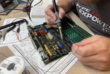 I located the clock generator on the board (chip UH7) and found a steady tone going out of pin 12, (C32M) and on both sides of resistor R28 on the underside of the board. I wasn’t sure how the clock signal was actually generated from the crystal itself (line C32G, pin 8), but when I measured it, I was getting nothing at all. WTF? I looked around for the +5v signal again and realized there was no continuity from 5v to the VCC pin on the crystal. Eureka! On the underside of the board, I worked backwards until I found there was very intermittent continuity through one of the ferrite beads (L13) that separate 5v from the VCC pin on the crystal. Sure enough, even though it looked visually perfect, when I put my iron on one side of it to wick the solder away, the entire component stuck to the iron with the broken off end staying embedded in the solder. 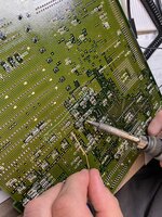 I pulled a ferrite bead from my donor board, cleaned the pads, soldered it in place, hooked it up, and turned it on. Boom: Good video, good boot, proper data bus activity, perfectly working clock. A ferrite bead on the underside of the board that the 5v rail goes through on its way to powering the crystal had cracked, causing an open line and no clock signal. While I was in there, I also removed, cleaned, and replaced the bodge wire with a shorter one that connected directly to a via. How’d it break? My guess is the board was flexed enough times while plugging in the 14-pin connector that it cracked. Takeaways for the future: Do the simple stuff first (check for power, check for reset, check for clock, check for data bus activity). Read the 680X0’s data sheet to get a working knowledge of what all the lines do so I have some idea of what to look for. Spend time probing working systems to know what a good state looks/sounds like. Even though I didn’t need it for this repair, I need to buy an oscilloscope and learn how to use it because some day it’s going to come in handy. 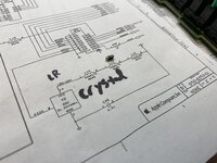 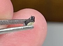 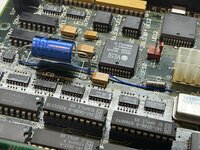 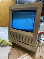 | |
| Posted by: AstroFirebird on 2023-09-11 19:58:56 What does the clock signal look like on the probe? | |
| Posted by: DJ68K on 2023-09-12 08:38:33 I threw a quick Youtube video up here: On page 2 of the Apple SE/30 schematics, when I probed for C32G (between crystal Y2 and chip UH7), I only got a constant tone. When I probed C32M coming out of UH7, it was much the same. Only from pin 18 (C16M) on the Glue Chip do I get anything that can be heard rhythmically and consistently by the logic probe. Perhaps C32G and C32M are too quick for my logic probe to pick up, hence my need to get an oscilloscope to learn more about what working signals should look like. But C16M is hooked up to CK (pin 1) on UG6 and UE7 PALs, and that's what Tom from Amiga of Rochester suggested using as a logic probe point for clock. | |
| Posted by: kefkafloyd on 2023-09-12 20:10:28 I returned home this evening, reinstalled the logic board into its proper Mac, and all is well. I'm not sure how the ferrule cracked. This SE/30 was stored in its original box in a basement for decades, as it was allegedly barely used before being put back into said box. I doubt the case had ever been cracked open before I opened it to clean and service the boards last year when I got it. But thanks to a lot of teamwork this board's back in business. I went back through my chat logs with DJ68K and realized that even before I opened the case for the first time this machine exhibited the "no video, no chime, but fans and hard disk are operating" symptoms. I even had a video I recorded of it doing that. It started working (well, working as in it powered on to a simasimac before being recapped) after I took it out and swapped it around to do tests. So I had simply chalked that up to storage or whatever and forgot about it. Therefore I have to think the ferrule was already partially faulty when I got it. After I recapped the machine it worked fine for a few months of infrequent usage. The intermittent failures happened more frequently as I moved it around for video recording purposes. Then I couldn't get it to boot again... and that's when DJ68K and I started investigating. Regardless, the lesson I've learned is "check for clocks!" 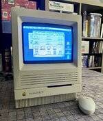 | |
Posted by: djc6 on 2024-11-24 17:38:20I threw a quick Youtube video up here: Thanks for this video! I have an SE/30 that was working, but suddenly last week stopped displaying video. I have the same logic probe. In your video pin 1 of UG7 (C16M) and pin 18 of the glue chip (C16G) sound the same - but on my board pin 1 on UG7 sounds "faster". C16G goes into UI6 on pin 2 - and it sounds the same there as on pin 18 of the glue chip. C16M then comes out of UI6 on pin 17 - and goes to PIN 1 on a few chips for the clock - it sounds noticeably faster than your video. Here is a video I took: I'm waiting on an oscilloscope to arrive. But I'm curious about this discrepancy between your board and mine. Here is a video I made: | |
| 1 |