68kMLA Classic Interface
This is a version of the 68kMLA forums for viewing on your favorite old mac. Visitors on modern platforms may prefer the main site.
| Click here to select a new forum. | |
| LC III schematic question - is this correct? | |
| Posted by: JC8080 on 2023-05-29 14:41:00 I am trying to fix a no-audio issue with my LC III, I removed the sound chip to clean underneath and check for broken traces. I used the Bomarc schematic to check continuity and everything was fine except pin 3. Per the schematic both pin 3 and pin 4 go to +8v. Pin 4 checks out, it has continuity to R2 and U4 pin 1, both of which go to +8v. Pin 3 has no continuity to R2 and U4, and also has no continuity to pin 4. Based on the schematic pin 3 and 4 should be tied together. Does anyone know if the schematic is accurate? Or if someone has an LC III handy, could you check for continuity between pins 3 and 4 of the audio chip? Thanks for any help! EDIT: I am checking continuity with the chip removed. Could it be that the chip needs to be installed for pin 3 to connect to pin 4 and go to +8v? I am planning on re-installing the chip later today and I can check then. 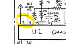 | |
| Posted by: max1zzz on 2023-05-29 14:56:02 Yep the schematic is correct, both pin 3 and 4 should be connected to +8V. I'm guessing the via right next to pin 3 has rotted out form cap goop | |
Posted by: David Cook on 2023-05-29 15:08:36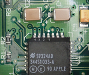 I agree. Just checked mine with a multimeter. Pins 4 and 3 are connected. Just for the sake of clarity, the image above indicates which are pins 3 and 4. | |
| Posted by: JC8080 on 2023-05-29 19:35:43 Thanks for the info. I gently prodded the pin 3 via with a pick and a bit of the via came off on the pic, so it makes sense the cap goo ate away the via. I recently recapped the board, so at least the damage won't continue. Is this something I can fix by bridging pins 3 and 4, or does pin 3 need to get +8v from somewhere else? I am not clear on where +8v comes from on this board, since the PSU outputs +5, +12, and -12. The schematic seems to show two transistors, 1AM and 1N0 that are involved with the +8v power, but I don't know nearly enough about electronics to know what's going on there. I also wasn't able to find those transistors on the board. The triangles with the dot in the center below are +8v. The only other place on the schematic I have found +8v is pin 1 of U4. 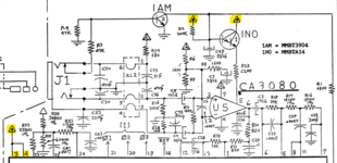 | |
| Posted by: David Cook on 2023-05-29 20:36:46 Just dab a little bit of solder between pins 3 and 4 to create an intentional solder bridge. See if that solves the sound problem. These pins are normally electrically connected to each other. No harm. Notice the traces are thicker leading to those pins to carry more current. They're just using more pins to carry more power into the chip -- not because they are actually separate electrically. 8V power is supplied by a 78L08 (U4) -- see below. The transistors you highlighted are used to connect/disconnect the mic amplifier when the microphone is removed/inserted. Avoids amplifing stray electrical noise when no microphone is attached. 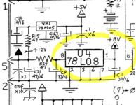 | |
| Posted by: JC8080 on 2023-05-29 21:00:06 Thanks, that's very helpful, I'll bridge pins 3 and 4 tomorrow and see if that brings the sound back. | |
| Posted by: max1zzz on 2023-05-30 10:55:01 Pins 3 and 4 are both connected to a internal +8V plane in the board so bridging the is fine, they don't need to connected to anything else first | |
| Posted by: JC8080 on 2023-05-30 15:35:09 Thank you all, I bridged pins 3 and 4 with solder and the audio works now. Sorry for the poor lighting on the photo. 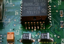 | |
| 1 |