68kMLA Classic Interface
This is a version of the 68kMLA forums for viewing on your favorite old mac. Visitors on modern platforms may prefer the main site.
| Click here to select a new forum. | |
| What is this symbol? - IIsi schematic | |
| Posted by: JC8080 on 2023-04-21 11:37:46 I'm troubleshooting an IIsi logic board, and I am not sure what this symbol means. I know it is the ground symbol but I don't know what it means here, running parallel to a trace. This is the 40mhz oscillator for the CPU. For context, when someone installed a 50mhz oscillator to overclock the CPU it appears they did not clean off the corrosive flux and the board around the solder joints is damaged. All of the oscillator pins have continuity to their destinations, but I wonder if corrosion could have gotten into the board between layers and caused an issue. Photos below. Thanks for any help! 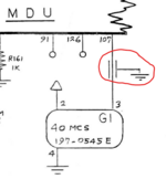 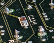 | |
| Posted by: olePigeon on 2023-04-21 11:53:46 With my considerable experience and breadth of knowledge, I do believe that is a "thingamajig." | |
| Posted by: Phipli on 2023-04-21 11:59:53 I think it is a trace guarded by a ground trace on each side for shielding. The clock output pin can cause noise on other traces, so you want to shield it to stop it causing noise where it isn't wanted. | |
Posted by: JC8080 on 2023-04-21 12:56:10I think it is a trace guarded by a ground trace on each side for shielding.Thanks, makes sense. I just thought of another question, maybe you can help with. One pin of the oscillator clearly goes to C114, however the schematic does not show any pins going to C114. Would it make sense that C114 would be in-line with either the +5 or the trace to the processor, and just wouldn't need to be on the schematic for some reason? I don't have my board and meter in front of me, so I'm not sure whether the pin with C114 is connected to the +5 or processor. | |
Posted by: Phipli on 2023-04-21 13:11:39Thanks, makes sense.I would expect C114 to be between 5v and gnd as a decoupling cap for the clock. I guess you might leave them out of a drawing because... well, every non-passive component has one and they're just... there. | |
| Posted by: Phipli on 2023-04-21 13:12:37 So between pin 2 and 4. | |
Posted by: JC8080 on 2023-04-21 13:28:40So between pin 2 and 4. Thanks for the help with this! | |
| 1 |