68kMLA Classic Interface
This is a version of the 68kMLA forums for viewing on your favorite old mac. Visitors on modern platforms may prefer the main site.
| Click here to select a new forum. | |
| Listing of parts by motherboard location Mac IIci | |
| Posted by: TheBilgeRat on 2023-04-10 20:05:07 Hello! First time poster. I recently picked up a nice clean IIci with the usual capacitor leaks. I am in the process of building a BOM for the capacitors and assessing the damage. The traces look pretty good so far, but the legs on a few components are pretty bad. What I'm looking for is a list of the passive components by location so I can order the correct parts. Some images: 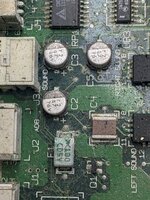 for example - what is this component at F1? 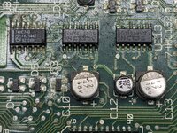 This SOT-23 at Q3 also looks pretty toast. It's a 1AMX but that doesn't come up with much at Mouser. I did find the BOMARC(?) schematic for this board but it does not list the values of the passives. Thanks again for any help! | |
| Posted by: joshc on 2023-04-10 23:54:20 Most of that looks fine to me - it should all clean up well with isopropyl alcohol and vinegar and a good soapy wash with a final isopropyl alcohol rinse. I'd do that first before ordering parts you might not need. If some chip legs are real dirty, the chip can be removed, the legs cleaned and the pads cleaned, and then soldered back. F1 is a fuse but I see no reason to replace it - it just needs cleaning and perhaps the solder joints need reflowing. Be careful with those types of fuses though, they come apart when you apply a lot of heat to them. Sometimes the 74HC132s need to be replaced for the startup circuit to work. The caps BOM is here: 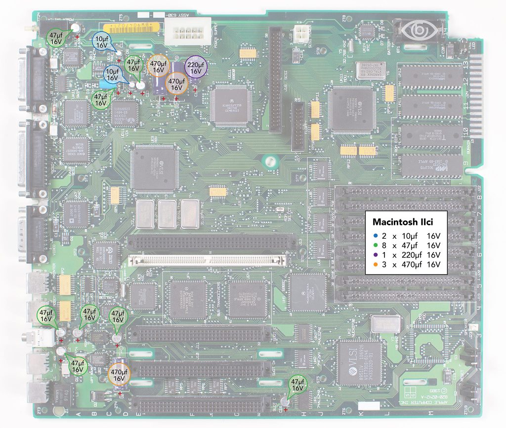
Macintosh IIci - Recap-a-MacThe Macintosh IIci has a cluster of five surface mount electrolytic capacitors near the startup circuit at the top left of the board...
 recapamac.com.au
| |
| Posted by: desertrout on 2023-04-11 14:52:14 Welcome! The IIci is a lovely machine, great to see another one getting the attention it deserves. 🙂 what is this component at F1?F1 is a fuse, schematics say SMD200-2 (so, 15V, 2A): 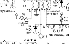 Q3 is a transistor - the Bomarcs show the transistor symbol and the '3', but not 'Q3'... then uses its own internal reference (1A) that it lists further above as a MMBT3904 (which will have 1AM on the package): 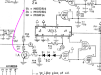 But @joshc is right - all that looks fine, just needs a bath and a good scrubbing and maybe some reflowing (then recapping of course, but you're on that train already). | |
Posted by: TheBilgeRat on 2023-04-12 18:32:43Most of that looks fine to me - it should all clean up well with isopropyl alcohol and vinegar and a good soapy wash with a final isopropyl alcohol rinse. I'd do that first before ordering parts you might not need.Thanks! Do you know why they suggest tantalums over modern electrolytics? | |
Posted by: joshc on 2023-04-12 22:43:27Thanks! Do you know why they suggest tantalums over modern electrolytics?People tend to choose tantalum capacitors because they are solid components - they won’t leak. If you used electrolytic caps again as replacements you would eventually need to replace them again. However some prefer them to keep the OEM appearance of the board. A good compromise is solid polymer capacitors which come in a similar can-style package to the original electrolytic capacitors, though I don’t tend to use them as I just find tantalum components easier to solder. A lot of Macs also used tantalums from the factory, especially Quadras. And if you look closely, a lot of Macs used both - and you’ll note it’s only the electrolytics that we need to replace now. All that said, tantalums have an interesting failure mode — if they short, are installed the wrong way (they are polarised), or otherwise fail, they explode. Usually it’s just a case of removing the exploded part and replacing it but in the worst cases they can damage the board or nearby components. I’ve never had that happen and I’ve recapped more than 50 Macs. | |
Posted by: mdeverhart on 2023-04-13 06:08:01All that said, tantalums have an interesting failure mode — if they short, are installed the wrong way (they are polarised), or otherwise fail, they explode.And along those lines, it’s generally recommended to derate the voltage rating tantalums by ~50% - for example, use a 25V tantalum on a 12V power rail, not a 16V (which would often be sufficient if you were using electrolytics or another capacitor type). Over voltage surges are another thing that can cause them to explode. | |
Posted by: joshc on 2023-04-13 09:23:39And along those lines, it’s generally recommended to derate the voltage rating tantalums by ~50% - for example, use a 25V tantalum on a 12V power rail, not a 16V (which would often be sufficient if you were using electrolytics or another capacitor type). Over voltage surges are another thing that can cause them to explode.True, though I’ve never had it happen to me — I think the risk is slim having recapped a lot of machines and never derated the caps. Something to be careful with it going for the next rating up (25v instead of 16v) is to check the package size will still fit on the solder pads otherwise soldering will be very difficult. | |
Posted by: mdeverhart on 2023-04-13 18:39:33I think the risk is slim having recapped a lot of machines and never derated the caps. Something to be careful with it going for the next rating up (25v instead of 16v) is to check the package size will still fit on the solder pads otherwise soldering will be very difficult.Wholeheartedly agree - the risk is relatively low (especially given the use case), and the package size difference is definitely a real potential issue. If you’re doing a new design (especially for a design that’s going to experience harsh mechanical or electrical conditions, or that has high reliability requirements), then you’d want to derate appropriately. For our hobby machines - probably not worth worrying about too much 😀 | |
| 1 |