68kMLA Classic Interface
This is a version of the 68kMLA forums for viewing on your favorite old mac. Visitors on modern platforms may prefer the main site.
| Click here to select a new forum. | |
| Seeking advice on LCII repair: PSU recapped but still grey screen and no chime | |
| Posted by: Death Walker on 2023-04-03 19:20:50 Hi everyone, I have a LCII which I bought on Ebay. Suffice to say the seller used "boots up" instead of "drive makes sounds" and "unit powers up" instead of "unit started once and died". I have recapped the PSU and it works again. I have tested it with a known-good LCIII and there are no issues. The LCII goes to a white/grey screen and there are no speaker chimes. If the unit is left on for more than 10 minutes, the speaker begun to scream a little. I have recapped the main board and now the speaker makes no screams or chimes. There is no battery damage. I observed no capacitor leakage or damage to the PCB. After reading about previous fix attempts, I have traced the tracks/via for the reset signals from U10 to the 68030 and are electrically intact. I have powered up the main board and the RST signal from #15U10 remains low for about 1 second, then rises to 5V without any dropouts. The fan spins up whenever the LCII is turned on. I have tried starting the LCII with and without memory simms, with/without HDD/FDD, even with/without VRAM. The LCII has a new 3.6V PRAM battery, have tried with/without it installed too. I noticed that after running for about 10 mins, the 68030 chip is quite warm to the touch. If it is doing something, I don't know what it is. No other chips are warm at all. I am using a VGA adaptor to an LCD monitor that I have tested on a known-good LCIII (640x480). The LCD monitor detects a 640x480 video signal when the LCII turns on and displays a grey/white screen with no flicker or lines. There is a 2x3 header pin block (J17) that has no connectors in it. I assume this is left empty so the GLU A20/A21 pins do not connect to the UB2 ROM pins 31/1 ? I have seen working mainboard photos where there are no header pins connected. I am assuming that because there is no chime at all, the ROM firmware isn't starting. I have removed the ROMs, and cleaned the sockets and ICs carefully and returned them to their original positions. I have checked their part numbers against the BOMARC schematics and they have been seated properly. Currently I'm not sure how to proceed. If I trust the seller and the unit was working before it went into storage, then I think I've followed all the simple-fixes that should have resurrected this beastie. I have no way to currently check ROM and memory ICs for faults, the known-good LCIII has different ROM/RAM components. Does anyone have any suggestions ? Have I missed anything obvious? Any suggestions would be appreciated. Thank-you for reading my plea for help. | |
| Posted by: joshc on 2023-04-03 22:07:16 Can I see some photos of your board please? | |
| Posted by: David Cook on 2023-04-03 22:16:27 Check the OE (output enable) pin on the ROMs. Pin 24 should go low if the CPU is trying to access the ROMs. If you have an oscilloscope or fast meter, check the output of the 25.175 MHz (G1), 31.3344 MHz (G2), and 32.768 kHz (Y1) crystals. Also pin 6 of the CPU. displays a grey/white screen with no flicker or lines.Do you mean the standard checkerboard pattern with rounded corners? If so, that would be a very good sign. Or do you mean a blank screen (no pixels). | |
Posted by: Death Walker on 2023-04-05 06:41:03Check the OE (output enable) pin on the ROMs. Pin 24 should go low if the CPU is trying to access the ROMs.Hi David, The OE of each ROM chip (pin24) all have the same 156.68kHz square pulse of 890nS pulse width and Pk-Pk of about 5.32v G1 has a sinusoidal output of 25.17MHz Pk-Pk 1.84v G2 has a much cleaner sinusoidal output of 31.35MHz Pk-Pk 1.76v Y1 has a sinusoidal output of 32.76kHz Pk-Pk 1.0v Pin6 of CPU, measured at pin B7 of the processor direct socket gives 15.67MHz, Pk-Pk 3.56v The screen is a single colour, a grey/white colour. There is no checkers or lines, just a solid single colour over the entire screen. The monitor says it detects a 640x480 signal. --------------------------------------------- | |
Posted by: Death Walker on 2023-04-05 06:50:28Can I see some photos of your board please?Hi joshc, I've attached some photos, let me know if there are any important areas you need images of. | |
Posted by: Phipli on 2023-04-05 06:55:33Hi joshc,Hum. Those photos do show signs of cap leakage. See how the solder in a number of areas is dull grey? That is due to corrosion. A perfect condition board has shiny silver on all of the pads. Pay attention to the areas around U10 and UA10. | |
| Posted by: Phipli on 2023-04-05 06:57:08 Could you share an equivalent picture to the second photo, but after the recap? | |
Posted by: David Cook on 2023-04-05 10:29:17Hi David, Those signals all look good. Okay, so you've got a solid clock and the ROM is being accessed. No sound. No video. If the LC II has entered diagnostic mode, that would help you eliminate some of the causes. See this link for details. Diagnostic Mode - mac68k - ConfluenceBasically, if any startup ROM test fails, the Mac enters a serial state where it accepts commands and outputs results at 9600 baud. Let's say you have a terminal program running on a working computer which is connected to the LC II. In the terminal program you type *V and the LC II should respond with version information. If that works, you know the LC II ROMs and CPU are at least partially working. From there, you can run various tests to maybe spot the problem. The trickiest part of this setup is making sure you've got the physical serial cable right. I used another computer (that worked) and a terminal program on another working computer to verify that I had a good cable and the terminal software had the right settings. I then switched the cable to my non-working computer (a IIsi) which was in diagnostic mode. The two major issues with getting a good serial cable setup are: * You need the transmit and receive pins to swap at some point (null modem cable or adapter) so that the transmit of one computer connects to the receive pin of the other, and vice versa * Many of the Mac cables I have in my collection seem to be wired to hook up to an imagewriter or something. They aren't wired like a standard serial cable. Here is a source of null modem cables: https://retrofloppy.com/products/ This may seem like a lot of work to maybe diagnose this LC II. But, once you have a good serial cable, you can use it on other Macs to transfer files or stuff like that. - David | |
| Posted by: Big Ben on 2023-04-05 11:35:10 Hi, Last time I had this exact problem was a bad connection on one of the ground pin of U10 preventing a proper RESET on all ICs. Sadly, I can't recall which one. | |
Posted by: Death Walker on 2023-04-05 14:51:49Could you share an equivalent picture to the second photo, but after the recap?Hi Phipli, I've never actually seen cap leakage firsthand, but I do see the effect it has on the board. I've seen old PCB solder tarnish after years of oxidation and assumed that was the case here. You will see a small red fly-wire connecting the +ve of C19 (47uF) to a via. Unfortunately the +ve pad partially lifted from the PCB when I was desoldering the cap. I did note the fibreglass under the pad was a strange black colour, so I alcohol swabbed it down before putting a small drop of superglue under it. The track to that pad was under the component but still electrically intact, so I fly-wired it just in case. Is the black fibreglass indicative of cap leakage ?? I have retouched some of the vias that were looking hollow and empty with some fresh solder. Should I electrically check continuity for each via through the board ? Or should I neutralise the cap leakage ? I have gently cleaned the board with IPA and cotton buds / toothbrush after decapping. Any thoughts ? | |
Posted by: Phipli on 2023-04-05 15:03:27Hi Phipli,Something to check is that there aren't any shorted vias under tantalum caps. I tend to take a photo after I initially remove all the caps so I can reference where the vias were afterwards. The tantalum have wider pads than electrolytics, so there can be issues. If you look at my boards you'll sometimes see one capacitor offset in a row, it isn't because I was drunk, I was just avoiding a via, honest. WfRT cleaning, if possible I'd give it a bath in a tray of IPA, perhaps scrub with a toothbrush, especially in the area discussed. Pads seem to lift more easily after cap leakage. | |
Posted by: Death Walker on 2023-04-05 17:19:34Those signals all look good. Okay, so you've got a solid clock and the ROM is being accessed. No sound. No video.Hi David, Thankyou for the useful information. I had no idea that so much diagnostics were built into these units. Colour me very impressed. I have hooked up a logic analyzer to the serial port but there is no automated data being transmitted by the LCII. I have transmitted 9600bps data @ 5V via a FTDI into the Rx pin but with no resulting reply. I will look at making a cable up over the weekend so the LCIII can hopefully communicate with the LCII with all signals and voltages correct. Jaycar has the 8 pin mini DIN connectors in stock. (Australia) There was initial activity on both the serial and printer ports, with state setting at power up and nothing else for many minutes (except a pin state change 5 seconds after powerup on DIN pin 2. Will keep the forum up to date with progress/ discoveries. Cheers. | |
| Posted by: joshc on 2023-04-05 17:39:20 What's going on here, does all this buzz out OK? The joint looks a bit dry and part of it looks like it might be touching a via it shouldn't. 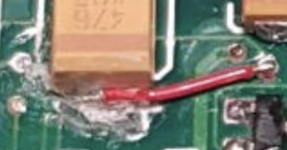 Is the black fibreglass indicative of cap leakage ??Got a pic of that? As you've used larger caps, I would go over all your work again and double check continuity of everything in all areas of the board you worked on. It can be tricky getting the solder to flow all the way to the pad underneath when working with larger caps than the originals. | |
Posted by: David Cook on 2023-04-05 18:38:31Hi David, Diagnostic mode settings are: 9600 baud, 8 data bits, no parity, and 2 stop bits. Note the stop bits is a little unusual. To verify it has diagnostic mode, I dragged up my LC II from the basement. When I power it on, I get the gray screen you talked about (so that's normal until startup tests pass). Not a checkerboard, just a plain gray with a legit video signal. Immediately I press CMD-Powerkey to generate an interrupt. I intentionally get Sad Mac chimes and the LC II enters diagnostic mode. Below is my annotated terminal output. 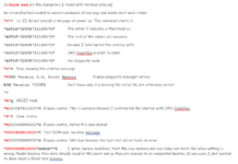 2 stop 2 stopImportant points: * The LC II did not provide any output message until I typed *5. * Maybe your startup tests work but something else bad happens after that. If you CMD-PowerKey at startup you can at least verify the CPU and ROM. | |
| 1 |