68kMLA Classic Interface
This is a version of the 68kMLA forums for viewing on your favorite old mac. Visitors on modern platforms may prefer the main site.
| Click here to select a new forum. | |
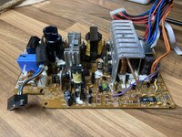
| Schematic and/or repair advice for Performa 6400 150W PSU (Apple part #614-0060, Delta model number DPS-150GB B) | |
| Posted by: TheMightyMadman on 2023-03-28 14:57:32 Hi all, The power supply has unfortunately died in my Macintosh Performa 6400 - it won't start up at all. It is a 150W unit, Apple part #614-0060, Delta model number DPS-150GB B. The PWM controller (TOP200YAI) had failed dead-short across all pins. I'm not sure whether this was the cause of the fault, or just a symptom. I did some basic checks on all of the other actives, and they seem OK in-circuit, and the two output rectifiers (STPS3045CP) seem OK out-of-circuit. I swapped the PWM controller for an uprated part, but the unit is still dead. Does anyone have schematics for this or a similar unit, please? Failing that, does anyone have any advice on how best to go about diagnosing it? Many thanks, Adam  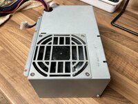 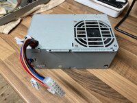 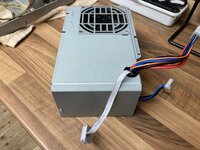 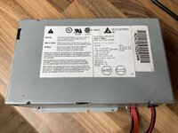 | |
| Posted by: TheMightyMadman on 2023-03-28 15:11:46 Some additional notes:
 | |
| Posted by: TheMightyMadman on 2023-03-29 14:01:30 R4 is indeed open-circuit - it's supposed to be a fusible resistor, probably 0.5W. I've ordered a suitable replacement part. 
FRN50J1R0/S Te Connectivity / Neohm Resistor , Fusible , 1R 5% , 0.5W | eBayFind many great new & used options and get the best deals for FRN50J1R0/S Te Connectivity / Neohm Resistor , Fusible , 1R 5% , 0.5W at the best online prices at eBay! Free delivery for many products.
www.ebay.co.uk
| |
| Posted by: superpete on 2024-06-22 00:49:45 Thanks for posting. I was struggling to find the fault on my own PSU until I saw your post. And of course R4 was in the Mega ohm range, with a tiny scorch mark. I've ordered a replacement. | |
Posted by: TheMightyMadman on 2024-06-22 01:09:10Thanks for posting. I was struggling to find the fault on my own PSU until I saw your post. And of course R4 was in the Mega ohm range, with a tiny scorch mark. I've ordered a replacement.I’m glad the thread has helped you out! Good luck with your repair. I’m sorry for forgetting to update this thread previously - after replacing both the PWM controller and fusible resistor, the PSU is working happily again! | |
| Posted by: superpete on 2024-06-22 02:10:49 Oh that gives me some hope! I'll have to (find) and check the PWM chip, but given postage is the dearest part of part orders might just add it to the cart in case. You wouldn't happen to have the part number handy? | |
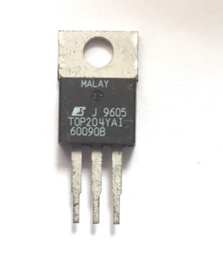
Posted by: TheMightyMadman on 2024-06-22 02:28:24Oh that gives me some hope! I'll have to (find) and check the PWM chip, but given postage is the dearest part of part orders might just add it to the cart in case. You wouldn't happen to have the part number handy?The PWM controller IC is a three-pin TO-220 package, I think it's IC1 near the fusible resistor - mine had failed short-circuit. Something will have caused that resistor to blow, so you need to find the cause of the issue before replacing the symptom - R4 is fusible for a reason. The original part is a TOP200YAI, which as you can see from the datasheet is only designed for 0-25W applications. I fitted a TOP204YAI as a replacement, which is rated for 75W-150W applications - I'm not sure whether this will make it more or less reliable in this specific application, so I'm not saying you should fit a TOP204YAI instead of a TOP200YAI, it's just what I did. 
TOP200YAI PDFPart #: TOP200YAI. Description: Three-terminal Off-line PWM Switch. File Size: 160.69 Kbytes. Manufacturer: Power Integrations, Inc..
pdf1.alldatasheet.com
TOP204YAI Power Integrations Three-terminal Off-line PWM Switch | eBay UK• 70% maximum duty cycle minimizes conduction losses. bandgap derived reference, bias shunt regulator/error amplifier. system against overload. bypass and start-up/auto-restart functions. handle both primary and secondary faults.
www.ebay.co.uk
| |
| Posted by: gyunix on 2024-06-25 04:23:37 Hi all, I am looking for a circuit diagram for the following power supply: DPS-150GB H. Can anyone help me with this? Many thanks, | |
| Posted by: Trash80toHP_Mini on 2024-06-26 07:13:04 Great topic! I have a couple of those to look at as well. Luckily no failures as of yet. Backup plan: pinout of that Apple version (undoubtedly non ATX compliant) of the 14pin female Molex power connector on the harness. The grlf is getting me a nice birthday present, all bits for a 250w PicoPSU conversion! 🙂 A 24pin to 14pin cable mod should do the trick for any ATX power supply conversion for the Alchemy/Gazelle machines, no? Also thinking of the Q630 and its non PCI offspring. Back directly on topic: thinking one of those 14pin adapter cables lopped off will make for easier testing all the Apple PSU's output values? Hot glue each line to a numbered, expected value board might be helpful? | |
Posted by: superpete on 2024-06-30 00:23:09The PWM controller IC is a three-pin TO-220 package, I think it's IC1 near the fusible resistor - mine had failed short-circuit. Something will have caused that resistor to blow, so you need to find the cause of the issue before replacing the symptom - R4 is fusible for a reason.Thank you so much. I pulled the TOP200YAI and it did appear to be shorted. I've ordered a TOP224YN as a replacement as I think it looked like it should more or less do the job as a replacement. It'll be a week to so before the parts reach me to try it out. | |
| Posted by: superpete on 2024-07-14 04:24:06 Success! The replacement resistor and PWM ic arrived this week and I installed it today. Everything is working as it should! | |
| Posted by: lsmi4126 on 2025-01-25 18:10:31 Hi folks - I'm struggling with the same PSU. Was totally dead with a burnt out R4 and shorted PWM (across all pins). I replaced both with: - PWM: TOP224YN - https://au.mouser.com/ProductDetail/869-TOP224YN - R4: https://au.mouser.com/ProductDetail/279-FRN50J1R0-S On power delivery - immediate pop and R4 is open short out of the board with a nice big scorch mark. The 3.3v lines appear to be shorted to ground. Is that expected? Any other ideas? Thanks in advance!   | |
| Posted by: powellb on 2025-10-27 11:52:21 Resurrecting an old thread here. I posted in another forum without luck. I am also rebuilding this PS, and in the image above from Imsi4126, you can see that below C1 is a large blob of glue. I removed that glue when replacing C1 because it was really holding it down. Later, I realized that R41 is in that glue, and it was gone. R41 goes from the positive side of C1 to R42, which then goes to R4. R42 is 700 kOhm and we know R4 is 10 Ohm. The question is: what value is R41? Can anyone test it for me (probably on the underside because of the glue)? I would greatly appreciate it. I'm guessing that they want a significant resistance to put R41 and R42 in series, so right now I am going to guess something like 1 MOhm (metal film resistor). Any thoughts? | |
| Posted by: powellb on 2025-10-27 18:36:23 Actually thanks to user obsolete, they determined that the value is 845K ohms. Hope that helps anyone who comes across this. | |
Posted by: freesofia on 2026-01-30 11:08:30Hi all,Hello, I have the same problem with a power supply model DPS-150GB H. On the first power-up it started without any problems. I shut the computer down, and on the next power-up it would not start anymore. | |
| 1 |