68kMLA Classic Interface
This is a version of the 68kMLA forums for viewing on your favorite old mac. Visitors on modern platforms may prefer the main site.
| Click here to select a new forum. | |
| Apple Techstep I have almost all of the ROMs here and some info! | |
| Posted by: jajan547 on 2022-01-10 15:52:19 Hello everyone, I know any information on the Apple TechStep is rare and limited and being that all ROM images are now lost online I would like to share all of mine with you so that you all can keep these devices alive and in good use. The ROMs I have are located below I have everything except for the fourth and last ROM. If need be I can program any ROM to a chip for you as I have multiple available and on hand. I hope this helps the TechStep community so that these are never forgotten! I also wanted to mention that if you are looking for chips to program with these ROMs you will need either an AM27C512 28 pin PLCC or a 27C1000QC 28 pin PLCC. I have only programmed the AM27C512's so far but I'm positive the 27C1000QC will work too as it was used in other ROM models. And please if anyone has the Fourth ROM image please share it. | |
| Posted by: jajan547 on 2022-02-11 20:31:51 Ok here is the fourth CPU Tests ROM | |
| Posted by: Skate323k137 on 2022-02-11 21:35:28 Very nice. Without having used these images, with my eprom programming exp I would wager the smaller files are for 27c512 and larger for 27c1000 as those chips are 512Kb and 1Mbit respectively. | |
| Posted by: ajacocks on 2022-02-12 06:44:49 Thanks very much @jajan547 ! I appreciate the hard work. - Alex | |
| Posted by: SuperSVGA on 2022-02-12 09:31:49 I just got Vol. 4 myself yesterday, plus all of the manuals. Curious how Vol. 1 always seems to be v1.1.1, while all the others are v1.0. I wonder if Vol. 1 v1.0 was with an EVT build or something, and they made improvements from there. | |
| Posted by: jajan547 on 2022-02-12 21:12:31 I have to admit this took some tracking down, I can't get CPU tests volumes 3 or 4 to work on that 271000QC chip. I was able to program 3 and 4 on the 27c512 but it wasn't operational, however all others work on the 27C512. What chips did you guys use or what chips are on the volumes 3 and 4 and are the silkscreens/motherboards different on the later ROMs. I ask because as it stands I am using the CPU tests Volume 1 ROM board and just swapping chips to use them. | |
| Posted by: SuperSVGA on 2022-02-12 21:27:09 Pretty sure the AM27C512 and the MX27C1000 have different pinouts, so if you're just putting the 271000 in it probably won't work. Here's some quick shots of Vol. 4: 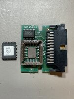 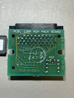 | |
| Posted by: jajan547 on 2022-02-12 21:39:16 Here is the ROM revision 1 board for the CPU tests 1 and 2 ROMS and no wonder, does anyone here have any experience with PCB design to design one of each ROM board. If so please PM me. | |
Posted by: Skate323k137 on 2022-02-13 07:01:56Pretty sure the AM27C512 and the MX27C1000 have different pinouts, so if you're just putting the 271000 in it probably won't work.Yes, totally different chips. It's not like a 27c256 to 27c512 situation where you can stack the roms, the 27c1000 (at least in DIP form) has more pins and 2x the capacity than a 27c512. I have not designed from scratch myself but I have tinkered with Fritzing with existing designs. Hopefully someone can create gerbers for these, this is one of those PCBs that is small enough where 1 and 10 cost the same to get made. | |
| Posted by: SuperSVGA on 2022-02-13 09:39:09 I could probably design something, though without desoldering the PLCC sockets it may take some time. Does anyone know what the black high density connector used to connect to the TechStep is called? | |
| Posted by: jajan547 on 2022-02-13 11:03:33 I have no clue but if you could make gerber files for both the community and I would greatly appreciate it. | |
| Posted by: SuperSVGA on 2022-02-13 14:28:39 I've got most of the design done, I'm just trying to figure out what the connector is so I can validate the footprint specs and potentially order some to test. I have a footprint right now that looks close, but it's better to know for sure. This is the only identifying mark I can seem to find on the connectors: 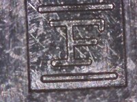 I assume that's the manufacturer, but I have no idea who it is. I've looked through a few possible manufacturers but haven't seen that symbol on anything yet. | |
| Posted by: stepleton on 2022-02-13 14:44:52 Pretty sure that's Fujitsu. | |
Posted by: SuperSVGA on 2022-02-13 14:51:53Pretty sure that's Fujitsu.I think you're right! Looks like it's part of the 210 series, likely the FCN-215Q040-G/0 connector. They seem to be discontinued, which will make this a bit trickier, but at least I think I've got the spec now. | |
| Posted by: jajan547 on 2022-02-13 15:00:09 I think I can find a replacement we can use today, did you say you know a bit of PCB design? | |
| Posted by: jajan547 on 2022-02-13 15:03:08 Is this it? Link here. | |
Posted by: SuperSVGA on 2022-02-13 15:21:54I think I can find a replacement we can use today, did you say you know a bit of PCB design?I'm working on a few designs at the moment. Some for the current hardware and some with modern compatible chips. Is this it? Link here.That does appear to be it, however it's odd that it says "Restricted Availability". It's also very unusual that out of the whole FCN-215 series, that's the only one that shows in stock on Mouser. | |
| Posted by: jajan547 on 2022-02-13 15:23:01 Are you able to purchase them? I can order some right now if you need me to send them to you? | |
Posted by: SuperSVGA on 2022-02-13 15:29:58Are you able to purchase them? I can order some right now if you need me to send them to you?I'll order a few for testing (assuming it lets me since it claims the part is not available from Mouser yet is also in stock), but I should be able to complete the designs without them. | |
| Posted by: jajan547 on 2022-02-13 15:34:50 If you send me the gerbers I can test on my end too. | |
| 1 > |