68kMLA Classic Interface
This is a version of the 68kMLA forums for viewing on your favorite old mac. Visitors on modern platforms may prefer the main site.
| Click here to select a new forum. | |
| LC TDK 699-0153 PSU Reference | |
Posted by: SuperSVGA on 2021-11-28 20:57:35LC TDK 699-0153 PSUSince there doesn't seem to be a lot of information on these LC power supplies, I thought I would share what I've been working on the past few months.My next goal is figuring out what everything on the board does in order to ease diagnosis, unfortunately I don't know much about SMPS or EE in general, so if anyone has any insights feel free to share. I vaguely understand what's going on but not enough to determine how specific voltages are sourced. Also if anyone can determine the specs of the two transformers, let me know. Board ComponentsAll the components on the board, with whatever specs I could determine. I wasn't able to identify most of the diodes.Spoiler content hidden. Unpopulated Board PhotosImages of the board with all the components removed.Spoiler content hidden. Populated Board PhotoA picture of a fully populated board, with replaced secondary capacitors.Spoiler content hidden. Redrawn Board PhotosThe PCB redrawn, mostly accurate.Gerber files are also attached in the post. Spoiler content hidden. Board SchematicA rough schematic of the board. Hopefully it's somewhat readable.Spoiler content hidden. | |
| Posted by: EffingController on 2021-11-29 14:03:24 Thank you so much for this. I recently obtained an LCIII. I recapped the power supply but I'm getting low voltage on the -5V rail. Hopefully this helps me track down the problem! | |
| Posted by: SuperSVGA on 2021-12-03 05:21:35 Correction to resistor R10, I believe it's actually supposed to be a 27KΩ resistor. I guess the first board I was looking at was discolored a bit. Also R54 should be 470Ω, not 460Ω | |
| Posted by: devius on 2021-12-05 01:40:51 This is great! I also recently drew the schematic for a TDK PSU, but it’s part number 614-0003. Seems similar enough to this one though. I can share it as well if there’s interest. | |
| Posted by: dan.dem on 2021-12-09 04:22:32 Thank you SuperSVGA this is a great step to successful repairs of the LC power supplies! While replacing the PS with a modern one is feasible, keeping the original ones working feels more satisfying to me. Please, can someone try to explain the function of the circuitry? This may hint about the missing component specs. My own knowledge is more (i.e. less) than rusty. Anyway, I would like to start discussing the schematic myself, even if there are more questions marks than useful information. Probably it provokes some, very welcome, corrections. Starting with the two fuses U1 and U2, I can only guess one is quicker. Then I see a filter consisting of C1, a double choke L1, and C2. ?? R1 makes sure, there is always a minimal load on the input circuit, and slightly dampens the CLC-filter?? C3 and C4 are actual in series and ?? make the mains voltage symmetrical to the device ground ?? CR1 is KBP06G, a 600V 1.5 A bridge rectifier. Probably, someone more competent may take over. Thank you! | |
Posted by: SuperSVGA on 2021-12-09 07:53:14Starting with the two fuses U1 and U2, I can only guess one is quicker.I probably should have made that more clear, there's only one fuse, but the holder is two parts making the symbol two sections. | |
Posted by: dan.dem on 2021-12-09 15:25:08I probably should have made that more clear, there's only one fuse, but the holder is two parts making the symbol two sections.Oh, sorry, I misread this. Anyway, my hope is that a better understanding of the circuitry leads to recommended procedures for error tracing and repair. This PS isn't a too complicated, and doesn't need very expensive equipment to repair - like a logic board does. My hope is we can build up some competence here necessary for reviving classic Mac's PS. | |
| Posted by: Bit-Worker on 2022-06-26 04:31:02 Hi Everybody! I have just gotten an LC II with a dead power supply, none of the voltages are right, they are mostly around 1-2V, nowhere near what they should, and I would like to attempt to repair. I never had Mac LCs before, but this PSU is so cute and pretty simple, its amazing! Thanks *SuperSVGA* for posting this info! It's priceless! And sharing this info, to be able to fix old gear, does more for the planet than charging for grocery plastic bags... 😀🙂😀 | |
| Posted by: Mauk on 2022-10-04 12:12:53 Hello there I have an old LC (32 years old) and am trying to repair the PSU at the moment. Hopefully all goes well🙂 | |
| Posted by: Phipli on 2023-07-29 12:47:39 Pretty seriously covered here, but since I've already collected the data and also recorded the series and make (series only for the Nichicons), I'll post it and my "map" here. 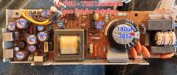 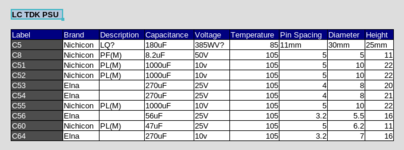 | |
Posted by: Phipli on 2023-07-29 13:45:15Pretty seriously covered here, but since I've already collected the data and also recorded the series and make (series only for the Nichicons), I'll post it and my "map" here.The ELNA caps are "RSG". Ironically labelled "long life" given they're the ones that have failed. | |
| Posted by: bnilsson on 2023-09-18 09:59:54 I have a Mac LC from mid 90's, I am trying to revive it. The TDK PS was dead to start, came to life after a few hours (as old electrolytic capacitors sometimes do). Then it suddenly died again. I read this thread with great interest. Replaced all electrolytic caps, the PC came back to life but died again. Overvoltage 14V/6V or nothing (tick-tick) dependent on the trimmer pot setting. Replaced the optocoupler. No good. Replaced the shunt regulator. No good. Looking at the PCB, it looked strange and icky. I rinsed the PCB in isopropanol a few times, the liquid in the bucket became severely yellow. I wiped it off and let it dry. Started the PS, now it worked perfectly. The old capacitors had leaked their electrolyte onto a thick layer on the PCB, shorting out all control circuitry. Lesson learned. BN | |
| Posted by: lostone on 2024-02-21 12:21:02 Has anyone found a modern equivalent of the C78N05 (IC51)? I've got the unstable -5V output after recapping (and looks like there may be electrolyte or something else on the board, cleaning has been in progress next would be depop and clean or ultrasonic. But before doing that I started looking at components to understand if something isn't working. I wasn't able to find the TDK MT1311 pinout and while there's a schematic above, I'm not clear what transformer output voltages should be feeding the C78N05. I can see the transformer has 2 inputs and 3 outputs so could throw low voltage AC on the inputs and measure the outputs unless someone else has already done that fun work. I also question if the C78N05 pin labels in the schematic are correct. Pin 2 is wired directly to the -5V output, so shouldn't that be output not input? I also wonder about transformer p6 being connected to C78N05 pin 2 not pin 1 as shown in the IC51 connections. Looks like transformer pin 5 is connected to pin 1 of C78N05 via the CR(diode). At least that's what my board looks like 7805 (not with the C prefix and N) had different wiring 1: input, 2: ground, 3: output. which this board would be wired similar to how you'd wire a positive regulator for negative output. The board appears to have this wiring: 1: to the transformer pin5 via the diode labeled CR53 (at least it looks and tests like a .5V diode) 2: to -5V output and transformer pin 6 3: to Ground If I test with the configuration in the schematic pin out I get .4V on the output, but if I wire up with the standard 7805 with 9V on pin 1 wiring I get -4V on the output with Vin 9V, 10V gets me -5V out. I found the Panasonic AN79N05 which at least has an N in the part number. I also noticed the Astec version of this supply uses a AN79N05. The 7900 is basically the negative output version of the 7800 regulator. What isn't clear is if the C and N characters in the C78N05 indicate anything. I suspect the C may just be a manufacturer label, but is the N important? Maybe Negative, maybe internal construction (NPN)? I don't know. Does anyone have specs on the transformer to check it's not internally shorted? I measured resistances and can see nothing's internally open, and appears to be 3 output wired together in groups of 2 (p1/2, p3/4, and p5/6 with schematic labels). Ground appears to be directly connected to p3 and not a CT with other pins. I know those are just two ends of each coil and how they get used depends on how the circuit is wired. I also had to the joy of accidently removing a pad while removing components so I get to enjoy some pad repair in this process. Luckily I will fully embrace the chance at something I enjoy. at least with these larger pads it can be fun! | |
Posted by: SuperSVGA on 2024-02-21 23:03:25Has anyone found a modern equivalent of the C78N05 (IC51)?I think something like the ST L7805ABV may work. Not all 7805s are quite the same and I don't remember what qualities are typically required, but the L7805ABV at least shows an example of it being used for negative voltage: 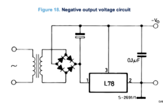 I also question if the C78N05 pin labels in the schematic are correct. Pin 2 is wired directly to the -5V output, so shouldn't that be output not input?I think the numbering may be incorrect on the schematic symbol, but the labels should be correct. It's been a while so I don't remember what library or part that symbol came from, I may have had to adapt it a few times and that messed up the numbering. | |
| Posted by: ben68k on 2024-03-21 08:55:17 Hi, Excellent work with the schematic. I have been working on one of these. Would someone with a working supply be able to measure the vcc voltage to the M51996P so I know what it should be? On mine I am getting about 40v. But the spec sheet for that chip says max vcc is around 30v. But when I look at the schematic and manually calculate based on resistor voltage divider from KBP06G output to pin 14 it calculates out to around 40v. How can this be? I am clearly missing something here. Thank you all ben | |
Posted by: ben68k on 2024-03-22 07:15:28Hi,Ok, so, maybe never mind; maybe I figured out my confusion. I was calculating everything from a dc static point of view and forgetting to take into account the dynamics of the startup time of the control chip. I think it all makes sense now. thank you ben | |
| Posted by: lostone on 2024-03-24 20:47:52 @ben68k since you're actively digging around in the circuit, could you do me a favor and check the voltages on the C78N05 (IC51). I can't figure out the input voltage (pin1), (with pins numbers 1, 2. 3 when looking at the label side). As noted a couple posts early I am unsure questions about the schematic labels/signals and my -5V is totally unstable and trying to figure out if that's regulating correctly. When I test with a DC supply as a negative regulator my output varies with the input voltage and I thought that should be constant over a wide input voltage range. Thanks if you can. | |
| Posted by: bnys on 2024-03-25 10:31:21 This may be a basic question but how do the colors on the wires correspond the different rails on this PSU? I assume black is GND, but what are yellow, orange, and blue? I have this PSU but it's completely dead and I have no way to measure them right now. | |
Posted by: cheesestraws on 2024-03-25 10:38:42This may be a basic question but how do the colors on the wires correspond the different rails on this PSU? I assume black is GND, but what are yellow, orange, and blue? I have this PSU but it's completely dead and I have no way to measure them right now. You probably want this page: https://old.pinouts.ru/Power/mac_lc_power_pinout.shtml | |
Posted by: lostone on 2024-03-26 09:28:45This may be a basic question but how do the colors on the wires correspond the different rails on this PSU? I assume black is GND, but what are yellow, orange, and blue? I have this PSU but it's completely dead and I have no way to measure them right now.One of several nice things about the Astec AA16-251 version of this supply (which also needed a restore after the two 120uF caps C17 and C20 were found to have 0 capactiance) is the wires are soldered directly into the board with silkscreens! Orange: +5, Yellow: +12, and Blue: -5. This is also the same connector found on the IIGS which also included -12V on a green wire at the unused pin 6 between yellow and blue wires. FWIW, this voltage color scheme has been a constant since the original Apple II. | |
| 1 > |