68kMLA Classic Interface
This is a version of the 68kMLA forums for viewing on your favorite old mac. Visitors on modern platforms may prefer the main site.
| Click here to select a new forum. | |
| 128/512/Plus 240V crowbar circuit - any ideas? | |
| Posted by: cheesestraws on 2021-09-07 04:15:16 I'm currently trying to draw out the schematics for the 240 V 128/512/Plus PSU, because it's slightly different from the 120 V one, and all the schematics out there seem to be for the 120 V version. Fortunately, since I don't know much about PSUs, it seems to be a very small variation on the 120 V one. However, when I got to the crowbar circuit, I got a little confused. Per Thomas H. Lee's document on the classic analogue boards and my own testing, this is what the 120 V board seems to have: 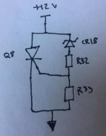 which is pretty conventional: if the 12V line gets too high, the voltage across R33 will get high enough to turn on Q8, shorting out the 12 V line. However, the 240 V one seems to do things a little differently, and I'd appreciate ideas as to why (and indeed whether my understanding here is correct). Here is the 240 V circuit: 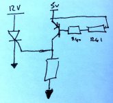 Instead of the zener-resistor combination, we have a 2N3906 PNP transistor, and instead of being hooked to the 12 V line, we're hooked to the 5V line (though the thyristor is still shorting out the 12V line, which makes sense). What I think is going on here is that because it's a PNP transistor, it'll switch on when the base is negative relative to the emitter; I assume that the two resistors are chosen such that when the 5V line gets to a certain "dangerous" level, the voltage drop across them will become big enough to cause enough emitter-base current to flow, turning on the transistor and pulling the thyristor gate high, shorting out the 12 V rail. But why? This seems much more Heath-Robinson than the zener way of doing it, and intuitively feels like it would be much more temperature-dependent. Am I wrong about this whole circuit (not implausible?) Was there a weakness in the 120 V one that this is trying to mitigate? Was it just cheaper? Eh? And, yes, I'm Big Clive-ing this up and doodling on a flipped printout of the PCB: 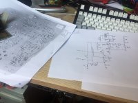 | |
| Posted by: techknight on 2021-09-07 05:44:27 Its possible the engineer for the international version ran into a parts availability problem, so he came up with a rather unconventional method of doing the task. And yeah you are correct about building the voltage drop at a certain point for the transistor to conduct, thus clamping the thyrister/SCR. The other thing is, engineers have their own "signature" method of inserting their own uniqueness in a design, kinda like handwriting, etc... and sometimes you just see unconventional stuff just because of the engineer himself. his/hers signature. Outside of this, I dont think the transistor vs diode would have any different in transition speed. Maybe... that could be why as well. | |
| Posted by: cheesestraws on 2021-09-07 06:16:05 Thankyou! That eases my worries that I'd misconstrued what was going on. | |
| Posted by: Cinan on 2021-09-07 15:59:16 Get work cheesestraws this will be very handy for all us non 120v'ers. | |
| 1 |