68kMLA Classic Interface
This is a version of the 68kMLA forums for viewing on your favorite old mac. Visitors on modern platforms may prefer the main site.
| Click here to select a new forum. | |
| Seeking CommSlot I and CommSlot II technical documentation, pinouts | |
| Posted by: aperezbios on 2020-12-15 18:41:05 Does anyone here have or know of any reference documentation from Apple for CommSlot II specs, and pinouts? and CommSlot I? I found the original CommSlot I pinout documented on Apple's website, as TA31498 | |
| Posted by: Trash80toHP_Mini on 2020-12-15 19:33:54 Hiya, I was working on this PM before I saw you post: You'll probably find the CSII pinout it in any of the CSII equipped series Developer Notes. I was looking at the 5400 DevNote earlier and found it. Apple calls it the PCI-Bus Communications Slot. Maybe someone has a link to that handy or to any other CSII machine DevNotes? If not, PM an addy and I can email it to you, haven't got the original title of the PDF for searching. Looked after you posted the thread, but I didn't see CSI in theQuadra/LC 630 series DevNote though. _______________________________________________________________________________________ In a tangent in another thread, you'd mentioned wondering about RPI Zero W for CSII Networking and a general lack of SBC compatibility with PCI, which sent me right off on a search: Article about the hack free RPi CM4 version with PCIe: https://www.electronicdesign.com/technologies/embedded-revolution/article/21145132/electronic-design-its-here-the-raspberry-pi-cm4-with-no-edge-connector Article about hacking off the USB3 controller from a standard Raspberry Pi 4 to get at its PCIe interface: http://labs.domipheus.com/blog/raspberry-pi-4-pci-express-it-actually-works-usb-sata-gpu/ YouBoobTube fun look at that hack: https://datasheets.raspberrypi.org/cm4/cm4-product-brief.pdf The full-on carrier board for CM4 appears to have a slot supporting its PCIe Gen 2 x1 interface. I'll make a working assumption it can be made to communicate bidirectionally with the "PCI-Bus Communications Slot Connector." The reduced 55mm × 40mm board size of the new CM card and interconnect fits it well enough into CSII Slot card cubic and onto some magical carrier card for that slot? That's as far as I got. It's all Greek to me, but fun finding the stuff. [🙂] edit: I see you've found the CS(I) pinout. moar: https://www.raspberrypi.org/blog/raspberry-i-compute-module-4/ I think I got all that into my reply in the new post, I hope it's helpful. Fab idea on slotting RPi into the PCI-Bus Communications Slot, hopefully it won't need to be jusdt a serial connection! [🙂] jt | |
| Posted by: Trash80toHP_Mini on 2020-12-16 08:59:16 Looks like it's inexpensive enough to connect PCIe to PCI. https://www.newegg.com/riitop-model-pcetpci-pci-express-controller-card/p/17Z-0061-00016?Description=PCIe to PCI adapter&cm_re=PCIe_to PCI adapter-_-9SIA6V85DD5236-_-Product https://www.newegg.com/p/17Z-00PR-03584?Description=PCIe to PCI adapter&cm_re=PCIe_to PCI adapter-_-9SIAKFCA219437-_-Product I wonder if it might be as simple as a PCI edgecard to CSII Slot edgecard signal adapter riser? Bodging a CM 4 carrier to the PCIe edgecard connector topside might complete the hardware hookup for testing purposes? If that works out, a CSII riser/CM 4 carrier might be reduced to a single card with the ASMEDIA1083 IC on board? I'd bet it could fit in the TAM. https://www.y-ic.com/pdf/afb5345064/ASM1083.pdf | |
| Posted by: aperezbios on 2020-12-20 09:57:43 Attached is a seven-page excerpt from the Apple Developer note PDF, which is 94 pages, and contains the authoritative info I was looking for. View attachment Apple 5500-6500 CommSlot II specs.pdf | |
Posted by: aperezbios on 2020-12-20 10:24:06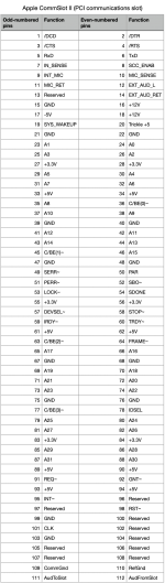 | |
| Posted by: Trash80toHP_Mini on 2020-12-20 13:02:39 Glad you found one of the DevNotes. Condensing the file into the specific pages will be handy, nice work. | |
| Posted by: Trash80toHP_Mini on 2020-12-21 05:02:39 First interesting thing I see about that doc is the lack of current rating for the +3.3V rail? | |
| Posted by: Trash80toHP_Mini on 2020-12-26 18:02:49 Just did a comparison of the PCI-Bus Communications Slot against the PCI control signal listing in the 5400 DevNote. PCI Expansion Slot AD [0Ð31] Address and data, multiplexed C/BE[0Ð3] Bus command and byte enable signals, multiplexed PAR Parity; used with AD and C/BE signals FRAME# Cycle frame; asserted to indicate a bus transaction TRDY# Target ready; selected device is able to complete the current phase IRDY# Initiator ready; master device is able to complete the current phase STOP# Stop; indicates the current target device is requesting the master to stop the current transaction DEVSEL# Device select; indicates that the driving device has decoded its address as the target of the current access IDSEL Initialization device select; used during configuration REQ# Request; indicates to the arbiter that the asserting agent requires use of the bus GNT# Grant; indicates to the agent that access to the bus has been granted CLK Clock; rising edge provides timing for all transactions RST# Reset; used to bring registers and signals to a known state INTA#, INTB#, INTC#, INTD# Interrupt request pins; wired together on each slot LOCK# Lock; indicates an operation that may require multiple transactions to complete. PERR# Parity error; used to report data parity errors during PCI transactions excluding a Special Cycle transaction. SERR# System error; used to report address parity errors, data parity errors during a Special Cycle, or any other system error that will be catastrophic. Expansion Features The PCI slot in the Power Macintosh 5400 computer does not support the optional 64-bit bus extension signals or cache support signals. For more information about the PCI expansion slot, refer to Designing PCI Cards and Drivers for Power Macintosh Computers. _______________________________________________________________________________________________________ CSII/PCI-Bus Communications Slot Control lines match up 1:1 with the exception of three missing interrupts of the four available on the 5400's PCI slot. 1 /DCD 2 /DTR 3 /CTS 4 /RTS 5 RxD 6 TxD 7 IN_SENSE 8 SCC_ENAB 9 INT_MIC 10 MIC_SENSE 11 MIC_RET 12 EXT_AUD_L 13 Reserved 14 EXT_AUD_RET 15 GND 16 +12V 17 -5V 18 +12V 19 SYS_WAKEUP 20 Trickle +5 21 GND 22 GND 23 A1 24 A0 25 A3 26 A2 27 +3.3V 28 +3.3V 29 A5 30 A4 31 A7 32 A6 33 +5V 34 +5V 35 A8 36 C/BE(0)~ 37 A10 38 A9 39 GND 40 GND 41 A12 42 A11 43 A14 44 A13 45 C/BE(1)~ 46 A15 47 GND 48 Gnd 49 SERR~ 50 PAR 51 PERR~ 52 SBO~ 53 LOCK~ 54 SDONE 55 +3.3V 56 +3.3V 57 DEVSEL~ 58 STOP~ 59 IRDY~ 60 TRDY~ 61 +5V 62 +5V 63 C/BE(2)~ 64 FRAME~ 65 A17 66 A16 67 GND 68 GND 69 A19 70 A18 71 A21 72 A20 73 A23 74 A22 75 GND 76 GND 77 C/BE(3)~ 78 IDSEL 79 A25 80 A24 81 A27 82 A26 83 +3.3V 84 +3.3V 85 A29 86 A28 87 A31 88 A30 89 +5V 90 +5V 91 REQ~ 92 GNT~ 93 +5V 94 +5V 95 INT~ 96 Reserved 97 Reserved 98 RST~ 99 GND 100 ReservedÔ 101 CLK 102 Reserved 103 GND 104 Reserved 105 Reserved 106 Reserved 107 Reserved 108 Reserved 109 CommGnd 110 RefGnd 111 AudToSlot 112 AudFromSlot I'd tried to hijack slot specific signals onto a three slot riser card in lieu of its standard jumper card lines and failed. Now I'm wondering about rewiring the CSII connections to convert it to a PCI Slot at whatever ID its single interrupt puts it? Designing PCI Cards and Drivers for Power Macintosh Computers doesn't even have a PCI pinout listing! | |
| Posted by: Trash80toHP_Mini on 2020-12-27 06:12:42 I hope my analysis of CSII is helpful. Had to replace delimiting tabs with spaces to get a clear presentation. But I've got simple .TXT/.RTF and AppleWorks spreadsheet files worked out if the raw data would be of help, though it looks like you've already got it into spreadsheet format? I'll start a new thread about PCI conversion antics if I put together information. Can't wait to see what you come up with about hooking Pi Zero directly to the slot, got a progress report to share? | |
| 1 |