68kMLA Classic Interface
This is a version of the 68kMLA forums for viewing on your favorite old mac. Visitors on modern platforms may prefer the main site.
| Click here to select a new forum. | |
| More Video Card probems-Micron Xceed 306 | |
| Posted by: JT737 on 2020-05-06 06:29:16 Hello everyone, As I sit here in my electronics room/Zoom office, I figured I'd ask a question. I have a Micron Xceed 306 video card that I bought off of eBay about a month ago. The good news is that it somewhat works; but that's the bad news as well! Half of the displayed video (The lower half displayed on the screen) is (somewhat) alright, but the upper-half of the video has vertical lines going through it, giving the displayed image a jagged appearance. So I took an educated guess at what the problem might be, and replaced the two Sigmatel 74F82n chips, which from what I can tell are 10 bit buffer chips. Unfortunately, no luck. Has anyone else here had a Micron 306 card with this problem? Any ideas at what other chips I should be looking at? Thanks! 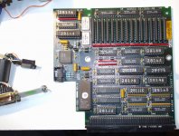 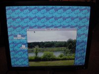 | |
| Posted by: techknight on 2020-05-06 07:25:22 it could literally be any one of those logic ICs. could be the 574s, could be alot of things. could even be the RAM. Unfortunately I dont think the crystal ball approach would work here. Might need to use a oscilloscope, or at the minimum, a logic probe and look for stuck lines. | |
| Posted by: Bolle on 2020-05-06 13:14:43 That’s screaming for bad VRAM or a stuck line on one (or more) of the 574s that mux the video data output. I posted the schematics for that card somewhere in the hacks section, that might help you understand the data flow on the card. | |
| Posted by: JT737 on 2020-05-06 19:23:41 Thanks @Bolle. I'll take a look for the schematic that you posted. A bad Mux.....that makes sense. Hopefully that's it, and not one of the VRAM chips. | |
| Posted by: Franklinstein on 2020-05-06 21:59:15 I imagine it would be something in the VRAM section. See if and how much the problem changes at different resolutions or bit depths. Also, it appears that the window is exposed on your EPROM. You could potentially have corrupted data in there. | |
Posted by: Bolle on 2020-05-07 00:27:57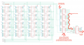 This might help. I'd actually poke at the 574s first. The EPROM probably is fine, otherwise the card won't show up or even produce an image. | |
| Posted by: JT737 on 2020-05-07 06:35:40 Thanks @Bolle! Also, I have a dumb question: what is the easiest way to test them (I'm assuming while it's running in the computer)? I currently don't have an oscilloscope (But I'm planning on buying one) but i do have a very nice fluke multi-tester. | |
| Posted by: JT737 on 2020-05-07 06:39:26 @Franklinstein-The problem seems to be consistent at any color setting or bit depth. As for resolution, the card only has one output- good old 640 x 480 VGA. | |
| Posted by: Bolle on 2020-05-07 08:35:04 You can check resistance of each output pin of the muxes (or the inputs on U22 for that matter) to ground or VCC. Same with the inputs on all 4 muxes. This might give you a hint if one of them is shorted if you’re getting low resistance somewhere or a value that vastly differs from the others. | |
| Posted by: JT737 on 2020-05-11 09:03:45 I tested out the 574 chips and found one that had some odd resistance readings on one of the inputs. So i bought some new old stock SN74ALS574BN chips, and when I finally got them in on Saturday, I soldered one in place of the one I thought was bad. Unfortunately, it didn't work 🙁 The other problem that I had was with where the chip was; because of it's location I had a hard time getting my hot tweezers around the chip, so I butchered things a little bit when I extracted it-ugh. I did try to remove as much of the solder first using solder wick and a solder sucker, but it still wasn't very smooth. A decent de-soldering gun is also on the list of things to buy in the next month.....I wish I had the money for a Hakko one. 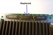 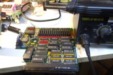 | |
| Posted by: techknight on 2020-05-11 12:22:22 if you were going to go through that extreme effort, I would have changed out all 3 of them. | |
Posted by: Bolle on 2020-05-11 12:36:13on one of the inputs.Might also mean that one of the VRAMs connected to that input is bad. Did you check the resistance again after replacing the chip? | |
Posted by: techknight on 2020-05-11 12:40:24Might also mean that one of the VRAMs connected to that input is bad. Its possible, one of the VRAMs has a stuck address or data line dragging that bit down on the bus. | |
| Posted by: JT737 on 2020-05-12 07:43:24 @Bolle - I did. And it appears that it's giving me the same wonky readings. Only question is where would I get new memory chips for this. Their are 16 of them on the board for what I would assume is a total of 1024k, so each chip must be 64k? There are these on eBay, but while they are in the right package, they're not the same: @techknight- It's definitely looking like that! | |
| Posted by: JT737 on 2020-05-12 09:00:41 Also @techknight-After the difficulty that I had replacing the one chip, I've decided to wait on replacing the others until I get a de-soldering gun. Just can't get my hot tweezers in there, and for some reason I wasn't having much luck this time using solder wick and my one-shot solder sucker. | |
| Posted by: techknight on 2020-05-12 11:05:56 you wont have any luck, its a multi-layer PCB and the only shot you would ever have is if the PCB was preheated, and fresh solder flown into the joints before using desoldering wick. aka, a PITA. | |
| Posted by: macsonny on 2020-08-25 18:57:43 I managed to pick up one of these cards but I don’t have the adapter cable to go from card to video connector. Does anyone have the pin out from the card connector to the video connector so I can make my own cable? | |
Posted by: Bolle on 2020-08-25 19:04:35I managed to pick up one of these cards but I don’t have the adapter cable to go from card to video connector. Does anyone have the pin out from the card connector to the video connector so I can make my own cable?This should be it: 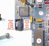 /CableOK should be grounded for the card to activate the signal outputs. Freq_Sel selects either of the two oscillators for the pixel clock when pulled to GND or VCC. The other signals can be wired up straight to a VGA connector. | |
Posted by: macsonny on 2020-08-25 19:35:12This should be it:Thanks for this guidance. I also found the attached pin out info. Based on this pin out and what you provided I think this is the connector cable: XCEED CARD -> DP-15 PIN 1 -> PIN ? PIN 2 -> PIN ? PIN 3 -> GND (PIN 1) PIN 4 -> PIN 3 PIN 5 -> GND (PIN 1) PIN 6 -> PIN 2 PIN 7 -> GND (PIN 1) PIN 8 -> PIN 5 PIN 9 -> GND (PIN 1) PIN 10 -> PIN 9 PIN 11 -> GND or VCC PIN 12 -> GND (PIN 1) Does this look right? Also, what does PIN 1 (VGASYNC) and PIN 2 (VGAVSYNC) on the XCEED card connector connect to on the DB-15? 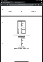 | |
| 1 > |