68kMLA Classic Interface
This is a version of the 68kMLA forums for viewing on your favorite old mac. Visitors on modern platforms may prefer the main site.
| Click here to select a new forum. | |
| IIsi death chimes after re-cap and then worse | |
| Posted by: jessenator on 2019-03-14 17:18:06 Got the new 40MHz oscillator installed and that was the last piece to the puzzle. Hooked up and soft-powered on: 1) chimes of death, nothing on screen 2) clt+apple+pwr : chimes of death, nothing on screen (flashes gray with colored bars on keyboard reset) 3) clt + apple + pwr: chimes of death sort of: garbled / distorted sound. Nothing on screen (flashes gray with colored bars on keyboard reset) 4) " completely garbled /distorted sound. nothing on screen See video: (flashes gray with colored bars on keyboard reset) https://drive.google.com/open?id=12fgLSUDysoQOdSuXx97JIphOYHwnKVYa HDD spins, fan spins... oscillator is oriented correctly in my socketed setup (at least the sharp corner is in the right place). great. What should I do to start diagnosing the problem? | |
| Posted by: jessenator on 2019-03-14 17:28:42 Update. let it sit, tried again. now no sound on boot. monitor is blank, solid grey on keyboard reboot. So I'm guessing it's not the PSU... | |
| Posted by: jessenator on 2019-03-14 17:43:59 Here's the p/n of cap that I purchased for the main board replacement and the larger radial caps | |
| Posted by: AwkwardPotato on 2019-03-14 18:26:23 Do you have the original oscillator available to swap in and rule that out as an issue? Pictures of the top & bottom of board might also be helpful for identifying any mistakes. | |
| Posted by: jessenator on 2019-03-14 18:31:41 I wish. 🙁 I accidentally broke one of the leads during removal. It's the original 40mhz. I have a 50MHz i could try, I guess... | |
| Posted by: jessenator on 2019-03-14 19:09:47 Well, I found one cold joint... C31. I'll see if I can get that one re-connected. I think that was one of the first I did. I'm just lightly twisting them laterally with tweezers to see and that's the only one that popped loose. | |
| Posted by: jessenator on 2019-03-14 19:26:00 Nope. Only difference now is the screen is a light blue with a very faint pattern... tried the other oscillator and no change. | |
| Posted by: AwkwardPotato on 2019-03-14 19:42:53 Hmm. You mentioned that you broke a leg off the old oscillator; I wonder if it's possible the through-hole for it was damaged too, resulting in loss of the clock signal to some components (unless it was broken off after it was removed from the board in which case disregard this)? Also wondering if given that it worked before recapping, there were traces damaged while it was being worked on, hence causing it to have this issue after recapping. Close-up pictures of the areas around the replaced capacitors might help with spotting such damaged traces. | |
| Posted by: jessenator on 2019-03-14 20:04:42 Well I think I see a possible problem... **** I thought I was being so careful. I'm not a complete spanner, I promise. Is is that trace below the oscillator? pixels warning) Yes there's a radial cap... I had to re-solder one of the SMDs and the contact snapped and I didn't want to spend $8 to ship one cap... Top:  Bottom:  | |
| Posted by: AwkwardPotato on 2019-03-14 20:15:15 That may actually be the problem: 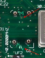 Trace on the bottom is severed, and the two on the top are suspect. | |
| Posted by: jessenator on 2019-03-14 20:17:14 Now I'm really out of my wheelhouse... What's a suggested course of action to repair the severed one? Thank you, for looking at this, by the way | |
| Posted by: jessenator on 2019-03-14 20:29:36 Looks like I could test continuity at these two on the bottom, based on where the trace goes on the top. 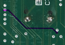 Edit: confirmed, no continuity Do I bridge these two? | |
| Posted by: AwkwardPotato on 2019-03-14 20:36:17 It's hard to tell but I'm not sure those two vias are the ones connected by that trace. I'd use an x-acto knife or something similar to scrape away the soldermask covering the trace, clean with IPA, tin the trace, and solder a wire on each side to jump over the cut. Don't worry about making it look perfect, it'll work just so long as there's a connection. By the way, it seems that the severed trace is also part of the CPU's data bus, which would explain why it's not working correctly. | |
Posted by: jessenator on 2019-03-14 20:39:22I'd use an x-acto knife or something similar to scrape away the soldermask covering the trace, clean with IPA, tin the trace, and solder a wire on each side to jump over the cut. Don't worry about making it look perfect, it'll work just so long as there's a connection.I'll give that a shot. Thanks! | |
| Posted by: AwkwardPotato on 2019-03-14 20:39:54 No problem 🙂 EDIT: One more thing I should mention is that when the oscillator is installed, make sure the oscillator's metal shell isn't touching the wire. | |
| Posted by: jessenator on 2019-03-14 22:18:37 I was just tearing up more of the trace and so I followed continuity to a better site to solder to. I now have continuity between the two halves of the trace. The bad news is it's still nothing but a garbled screen. I fear I've done irreparable harm to the motherboard. I did notice, too, that my PSU is making odd noises. not really a crackling, but a noise like there's something switching (not loud like the main power) or something, which unfortunately I can't replicate to record now... I'm resigned to write it off as a failure and part it out. I have another IIsi coming my way (spoilers) and I might test with that PSU. IF that's not the issue, I'm going to part it out. I feel like such a ****ing idiot. | |
| Posted by: jessenator on 2019-03-15 13:02:45 @AwkwardPotato thanks for all your help. I think it's a lost cause for me…maybe not for someone else. One final question I had is regarding the PSU. Is there a way beyond putting it into a donor IIsi to test whether it has issues or not? Since I'm parting it out, I wonder if I could give assurances that it's working by testing it. Or, will it do any harm to test it in a working IIsi? | |
| Posted by: Johnnya101 on 2019-03-15 13:06:37 I personally would sell the whole thing as a parts/repair machine. Dont separate anything. That ways you are not liable if a part doesnt work. | |
| Posted by: jessenator on 2019-03-15 14:07:29 That's a good plan, tbh. I'm in more of a dire need than I had planned, so I might have to go the ebay route to speed things up… | |
| 1 |