68kMLA Classic Interface
This is a version of the 68kMLA forums for viewing on your favorite old mac. Visitors on modern platforms may prefer the main site.
| Click here to select a new forum. | |
| LC 575 board (in Color Classic) - funky vertical lines | |
| Posted by: KnobsNSwitches on 2018-03-30 09:10:31 I took a chance on an unknown condition LC 575 logic board for upgrading my Color Classic. The good news: it boots! The bad news: it looks like this: (don't mind the error message on the screen. I haven't moved over the right system enabler for the 575 board in the color classic yet. I just wanted to test booting yet) I don't see any obvious capacitor goo on the board, but I did give it a rinse in distilled water and a scrub with a toothbrush and the screen still looks like that. Any ideas of what could be causing the picture? 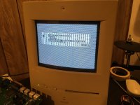 | |
| Posted by: beachycove on 2018-03-30 09:13:50 Reseat the 575 vram simm, or try another. | |
Posted by: KnobsNSwitches on 2018-03-30 09:36:34Reseat the 575 vram simm, or try another.There are 2 installed (I need to verify if they need to be in pairs), I have reseated and swapped their locations. I don't have any spares, I'll need to seek some out. | |
| Posted by: beachycove on 2018-03-30 09:53:12 A few years ago, I had one bad vram simm in a 575 logic board (installed in a CC too) that caused very similar anomalies. It’s possible that vram could explain your troubles. The nice thing in this case is that all vram is easily replaceable, as there is none soldered onboard. The bad thing is that you need additional vram Simms to test the possible fault. You have no other machine from which to borrow some? | |
| Posted by: beachycove on 2018-03-30 09:54:32 You are relying on the ResEdit hack, right? | |
Posted by: KnobsNSwitches on 2018-03-30 10:01:55You are relying on the ResEdit hack, right?Yes. A few years ago, I had one bad vram simm in a 575 logic board (installed in a CC too) that caused very similar anomalies. It’s possible that vram could explain your troubles. The nice thing in this case is that all vram is easily replaceable, as there is none soldered onboard. The bad thing is that you need additional vram Simms to test the possible fault.Sadly, no, the CC is my only vintage desktop. I have some 30 pin SIMMs and several PowerBooks, but nothing else to borrow some from. | |
| Posted by: beachycove on 2018-03-30 10:24:00 The resedit hack is all about the screen, so make sure that's done right before going further. I somehow missed the enabler reference in the original post, so maybe be sure the software is right first. | |
| Posted by: KnobsNSwitches on 2018-05-15 11:20:02 Just an update to this thread. I purchased some new VRAM from memoryx.com, but the symptoms persist. (I should note, the lines are visible on screen before booting goes anywhere, on the happy mac, 'welcome to macintosh' etc. ) I recapped the board, just in case, if nothing else to practice my soldering, but still have the same issue. I must keep digging. | |
| Posted by: Byrd on 2018-05-15 22:43:32 I've a similar issue with my LC575 board, is the Mac "usable" and does it boot to desktop? If so, still VRAM but could be a bad trace on the connectors themselves. I've not recapped mine yet. | |
Posted by: xboxown on 2018-05-17 12:06:25I took a chance on an unknown condition LC 575 logic board for upgrading my Color Classic.That is hot!! I do not know why..but I start picturing Apple // when I saw this picture. | |
Posted by: KnobsNSwitches on 2018-05-20 12:47:28I've a similar issue with my LC575 board, is the Mac "usable" and does it boot to desktop? If so, still VRAM but could be a bad trace on the connectors themselves. I've not recapped mine yet.I missed this response somehow. Yes, it is "usable" in that it does boot, but it's really hard to see any thing. ;-) | |
| Posted by: AlpineRaven on 2018-05-23 13:08:05 Can you send a pic of the VRAM modules up? Cheers AP | |
Posted by: KnobsNSwitches on 2018-05-24 08:32:33Can you send a pic of the VRAM modules up?Sure, I'm not quite sure what you meant by 'up', so here's the 2 VRAM simms, and then installed. 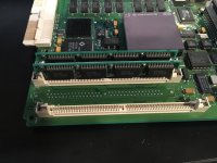 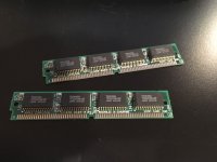 | |
| Posted by: Bolle on 2018-07-19 11:35:04 The board arrived at my place and I think I found the culprit already: 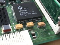 That's the RAMDAC. I quickly popped it off but everything looks fine underneath: 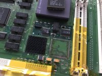 Also gave the chip a quick treatment, doesn't look too bad anymore: 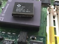 At least it still has all its legs connected and not rotten off yet. Let's hope it was just a failed connection outside of the IC and it did not start rotting on the inside. I will put it on again in the next days and see if it resoldering it already fixed the issue. If not I am going to try to carefully cut it open a little bit and see if the internal traces to the die are also corroded. Also took a quick look at possible donor machines... LC475, Quadra 605 and 610 (and maybe all the other Quadras as well) do share the same RAMDAC in case I need a replacement IC. | |
| Posted by: bibilit on 2018-07-20 01:56:57 Capacitor C29 probably was responsible for that mess, ugly soldering by the way. | |
| Posted by: Bolle on 2018-07-20 02:37:22 Was not going to say it as harsh as you did, as he said he used it as a board to practice soldering on. My first attempts have been worse I would say 😛 As a side note to @KnobsNSwitches: you used quite a lot of solder, you don't need that much with surface mount parts. Also be sure to heat up not only the pads but also the "legs" on the component itself as well to make the solder bond with them as well. I like to apply some solder to one of the two pads, heat that solder up and keep it hot while putting on the cap. As soon as solder bonds to the cap remove the heat and simply solder on the other side. That way you will also be able to solder the components down all the way and not have them sit on a tiny hill of solder. | |
Posted by: bibilit on 2018-07-20 05:42:24Was not going to say it as harsh as you didDidn't want to be rude. Yes, not enough heat on both sides. I try to use a minimum of solder on the each pad of the capacitor, this will keep the cap as flat as possible, heat one side until it will bond to the board, then i do the other side and use some more solder and heat on both sides. This will get solid and shiny welds. | |
| Posted by: KnobsNSwitches on 2018-07-20 06:22:58 Bolle, glad the board finally made it out of customs and am impressed you're getting to work on it right away. I appreciate the updates and the soldering tips. bibilit, yes, this was indeed my first soldering job. Thank you for clarifying, I thought you were being just being rude. I'm getting better but looking at my latest board the caps still aren't flat. I need a better way hold the cap down while heating one side at the time. Practice will make perfect, I guess. | |
| Posted by: Bolle on 2018-07-20 08:54:49 I can make a short video how I do it when putting the caps back onto your board if that helps. | |
| 1 > |