68kMLA Classic Interface
This is a version of the 68kMLA forums for viewing on your favorite old mac. Visitors on modern platforms may prefer the main site.
| Click here to select a new forum. | |
| How to mod an ATX PSU for 10 Pin Macintosh (for example IIsi, IIci, Quadra 700 and others) | |
| Posted by: MrGasS27 on 2018-01-24 02:43:32 Hi everybody! One year ago my IIci PSU got broken, I don't care about repairing old PSUs so I modified an ATX in order to use it on my Macs. I did some diagrams and a video to explain how to do this (audio is in Italian but I added english subtitles) 1) First I broke a 20 pin ATX male plug, the left part fits good in the 10 Pin PSU input. 2) Look to numbers under the PSU input on your Macintosh motherboard. 3) Follow the diagram I created, remove 3x GNDs, 3x +5V, 1x +12V, 1x -12V, 1x +5V_SB from the 20 Pin ATX male plug then put them into the adaptor you broke following my diagram (assure yourself that fits correctly into your motherboard) 4) Put a rocker switch between PS_ON (Green cable) and a GND (a black cable) for turning On and Off your Macintosh (you must shut it down it after doing Special > Shutdown) LINK TO MY YOUTUBE VIDEO: 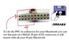 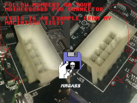  | |
| Posted by: IlikeTech on 2018-01-24 07:07:46 Did you know you can add soft power so that shut down works properly for like 5 dollars or less? A simple 74LS04 and 2 1k resistors works fine for this exact mod I did to my Q650, which uses the same PSU connector. | |
Posted by: MrGasS27 on 2018-01-24 08:39:46Did you know you can add soft power so that shut down works properly for like 5 dollars or less? A simple 74LS04 and 2 1k resistors works fine for this exact mod I did to my Q650, which uses the same PSU connector.Yep, I know, but personally I don't care, honestly I prefer the manual switch | |
Posted by: Jon183 on 2018-03-05 06:36:23Did you know you can add soft power so that shut down works properly for like 5 dollars or less? A simple 74LS04 and 2 1k resistors works fine for this exact mod I did to my Q650, which uses the same PSU connector.That sounds great, is there a guide on how to get that done? I would like to mount a SFX PSU into the original PSU shell for my IIci so it docks in like normal and has normal power on/off. | |
| Posted by: IlikeTech on 2018-03-05 06:44:11 I'll PM you the schematic when I get the chance! | |
| Posted by: Trash80toHP_Mini on 2018-03-05 08:27:47 Please post the schematic here in the open forums so it can be linked to if and when another of my lost threads is recovered: The ATX Gazette Therein we'll again find a listing of links to everywhere I could find information on the subject, here, 'fritter and every page in the wilds of the net. In the meantime, floofies thread on the subject of ATX is developing specific conversion contributions and info that's generally applicable to the conversion at hand: ATX PSU Conversion Mapping That's the first place I recall you mentioning your work on the 650, a link from here to there will be most helpful in the future. | |
| Posted by: IlikeTech on 2018-03-05 08:32:51 Okay, will do! | |
Posted by: IlikeTech on 2018-03-06 07:11:36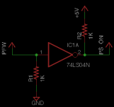 Here you go! This is the schematic I used. It was the same as the original but I had to use 1K resistors. IC Power connections are assumed. You need to connect 5v to the 5VSB line of your PSU. | |
| Posted by: Jon183 on 2018-04-30 21:53:36 How do I apply it to a iici? I got the softpower stuff and a SFX PSU to retrofit inside the shell but I dont know what to do for PFW, although I understand what to do for my 8100/110. | |
| Posted by: trag on 2018-05-01 14:32:38 Here's a 10 pin plug from Molex which would probably avoid the need to break an ATX connector. The only issue is that I have not tried it and so I don't know if the shape of the individual little plugs and receptacles (one per conductor) match with the IIci's connector. Molex 10 pin Mini Fit Jr. Plug Housing Molex part number 39-01-2100 | |
| Posted by: IlikeTech on 2018-05-02 06:58:43 That is what I used I think. I didn't break an ATX connector. | |
| Posted by: trag on 2018-05-02 12:12:51 But it was step #1 in the original poster's report. And folks might like to be able to get a proper 10 pin connector. | |
| Posted by: Trash80toHP_Mini on 2018-05-02 14:56:55 My IIsi has the same connector, but I've been working on a PCB that will take care of the conversions by soldering the stock connector's wiring into thruholes with traces connected to holes for a Teensy ATX PSU that fits in the stock can. The PCB will have pins matching the OEM header row for plugging in the the AC plumbing plate at the rear, including the fuse on the PCB. One day. :🙂 I Hate the notion of wire splicing. Someone used a Molex tool to do the job properly in his conversion. Anybody got a link to that hack? | |
| Posted by: trag on 2018-05-02 15:35:48 Just for you, jt. 🙂 I think this one will mate with the connection on the IIci and IIsi (not 100% certain) and it is a circuit board mount. So, you could build your custom board to go inside your power supply mod, and mount this connector on it to mate with the IIci or IIsi. But I'm basing my compatibility assumption on a reading of Molex's literature, and I may have misinterpreted it. https://www.digikey.com/product-detail/en/molex-llc/0015247101/WM17737-ND/1633800 Molex 0015247101 https://www.mouser.com/pdfdocs/MolexBMIBoard-to-BoardSystem.pdf | |
| Posted by: Von on 2018-08-10 22:47:55 Exciting times. My 2nd SeaSonic PS arrived today and is on its way into my IIsi: 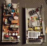 Stock entrails are on the left, SeaSonic out of its case are sitting nicely within the top part of the IIsi PS. My plan is to remove the stock entrails all except the plastic molex connector. I will remove the original wires and then wire directly to from the SeaSonic with no splicing required. While I could easily find a PS switch that would fit in the monitor power port at the back of the case, I'd rather have this work like stock with the power button on the keyboard. I get how to run the wires from the PS to the plastic plug. What I don't get is how to pull this off: Did you know you can add soft power so that shut down works properly for like 5 dollars or less? A simple 74LS04 and 2 1k resistors works fine for this exact mod I did to my Q650, which uses the same PSU connector. Here are 2 images from higher up in the post: 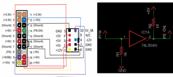 Can someone please explain to this non-EE exactly what I need to do enable the diagram on the right? I don't get what connects to what... THx!! | |
| Posted by: IlikeTech on 2018-08-11 04:24:55 Is the seasonic PSU ATX? | |
| Posted by: Von on 2018-08-11 13:19:12 Yes, ATX12V Flex/Mini 1U This is the description on NewEgg | |
| Posted by: Von on 2018-08-12 19:23:57 The plot thickens on my attempt to put the SeaSonic PS into my IIsi chassis. As I was removing the stock wires I noticed that all 10 of my wires are filled. The photo shows the ground removed from position 5:  Here +5 red (position 4) and ground (position 5) are removed. Now there is a clear view of position 9 with a blue wire: 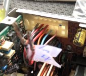 Diagram from this post has position 9 empty. I have googled for a bit and even tried to fetch this from the way back machine with no luck http://www.xlr8yourmac.com/systems/MacinPC_ATX_case/images/PC-MAC_PS_pinouts.jpg Does anyone know what position 9 might be? THx | |
| Posted by: superjer2000 on 2018-08-12 21:11:49 I think that pin 9 is the Power On signal for the Power Supply - To get the stock power supply to turn on, you would jump pins 9 and 10 which are +5V on pin 10 and Power On sense on Pin 9. That's where the control circuit you have above comes in. My understanding (potentially wrong!) is: When the soft power is triggered, it generates 5V to pin 9, but the ATX supply expects ground for it's power on signal, so the circuit swaps the +5V for GND which allows the ATX supply to turn on.  | |
| 1 > |