68kMLA Classic Interface
This is a version of the 68kMLA forums for viewing on your favorite old mac. Visitors on modern platforms may prefer the main site.
| Click here to select a new forum. | |
| SE/30 Symtom ID | |
| Posted by: IlikeTech on 2018-01-22 07:08:16 View attachment 13320 What symptoms are these? Wierd. I am considering buying @Alex's SE/30 Board, and I am curious as to what the symptoms are. BTW: How many layers is the SE/30 board? Thanks | |
Posted by: PB145B on 2018-01-22 07:11:18BTW: How many layers is the SE/30 board?I want to say it’s three but I don’t know for sure. @techknight should definitely know though. | |
| Posted by: bibilit on 2018-01-22 08:15:36 IIRC 4 layers. | |
| Posted by: techknight on 2018-01-22 08:17:55 Yep. 4 layers. That result has multiple causes. Since its not a consistent simasimac, that means there is damage to the video circuit. Could be just cap residue, but could have bad traces there. And if there is no chime, then you need all new caps of course, as well as possibly fixing ROM traces. | |
| Posted by: bibilit on 2018-01-22 08:40:49 Battery damage ? | |
| Posted by: Alex on 2018-01-23 03:06:25 Hello I just wanted to chime in, here are the remaining images of the logic board that were already posted by me in the past in another post on 68kmla. IlikeTech did show interest in the board and these photos are of the board in my SE30. I have a few more pictures that I will post here. There are many more photos that I will add here. One thing is for sure, when I get the new board I will make high res images of this faulty board and post it to IlikeTech. My goal here is to give the board a good home and to provide as much information in the most honest way I can. My knowledge is limited but of course the visual inspection phase surely helps. So all the photos here are photos I took a few months ago. As told IlikeTech when I received the machine, I already knew there was a logic board problem as the photo IlikeTech posted at the top was the image I saw on the auction site. So turning it on would be a risk in my view. I simply opened the machine and cleaned up the entire machine in and out, the board however was only visually inspected and a few photos taken because I did not have the knowledge to fix it, being soldering skills (which I am not too bad at now but not then) and zero knowledge of multimeter use, now I can only check continuity and measure capacitors for their values — anyway I have a lot to learn but I think these images should help. I will take more photos when I get the new board so that IlikeTech can make an informed decision on whether he would like to work on this board or not. —Alex 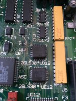 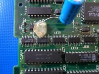 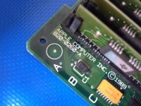 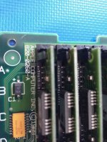 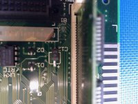 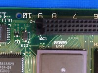 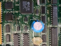 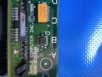 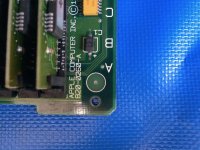 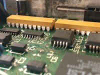 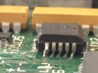 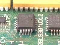 | |
| Posted by: Alex on 2018-08-14 08:22:56 I am revisiting this thread because I just spent the last two days repairing the original board that shipped with this Mac. I purchased another MOBO which I replaced caps on and it's all good but I felt sorry for the original MOBO so I thought I should try to repair it as meticulously as I can. I still need to install BT1 (battery holder), axial capacitors C1 and C11. It still needs to be cleaned a little further as there are still traces of cotton threads from the Q-tips. What I found wrong with this board: Two pulled pads, some damaged traces (continuity broken)
C12 and C6 missing pads C12 was temporarily fixed to the board using a thin Cooper wire in place of a pad, continuity is good. C6 also had a missing pad and part of the trace leading from the pad was broken. In this case I simply used a jumper cable from the negative side of the tantalum cap to the chip. I left some pics of the progress. I have yet to test the board in the SE/30 two axial caps to install and I need to clean up the cotton residues that I carelessly left behind. I am taking a few days off this project but will report back as I progress a little further. 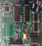 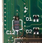 | |
| 1 |