68kMLA Classic Interface
This is a version of the 68kMLA forums for viewing on your favorite old mac. Visitors on modern platforms may prefer the main site.
| Click here to select a new forum. | |
| Q605/LC475 capacitor connections | |
| Posted by: mrpippy on 2015-09-20 01:19:12 I've been recapping my Q605, some of the pads are in rough shape but I was still able to probe the connections easily. Here's the list I came up with: C35: 47 µF (+): +5V (-): GND C36 : 47 µF (+): +5V (-): GND C101: 47 µF (+): 12V (-): GND C105: 47 µF (+): +5V (-): GND C127: 47 µF (+): GND (-): -5V C128: 47 µF (+): 12V (-): GND C129: 47 µF (+): +5V (-): GND C136: 100 µF (+): +5V (-): GND C137: 100 µF (+): GND (-): -5V C149: 47 µF (+): C150 + (-): U30 pin 21 C150: 47µF (+): C149 + (-): U30 pin 24/25 C149/C150 are the ones I'm not sure about, especially the + side, I couldn't find any other point on the board that those two connect to. The trace between them does have a via which goes through to the bottom, but no traces coming out of the via. I've never gotten chimes or any signs of life out of this board, fan and HDD power up but no chimes before or after recapping, with a good battery installed. PSU voltages also look good even when the board is powered up. I thought that some of the RAM vias/traces under C127/C128 would be bad, but I've tested the RAM signals and they all seem to be good. Anyone have any ideas? | |
| Posted by: mrpippy on 2015-09-21 22:23:50 I fixed it!! 🙂 I saw that the vias around C35 didn't look so great, and started tracing to see where they went. I found one which tested ok to the bottom of the board, but for some reason wasn't connected to its trace on the top of the board. 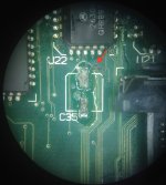 Turns out this is the main 12.5 MHz clock input to the SYNC pin of the MC88920 clock driver (down near the speaker connector)! I ended up running a wire from the bottom of the board (the easiest place to tap this signal) to pin 7 of the MC88920, and it works! 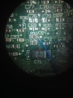 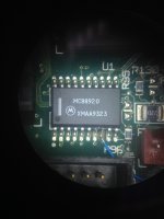 It even has a 32MB SIMM 🙂 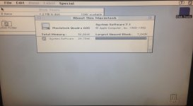 Anyone with a Quadra 605 / LC 475 that's not powering up even with new caps and a good battery should check that pin of the MC88920, it needs to have a square wave on it. | |
| Posted by: rsolberg on 2015-09-22 15:13:18 Congrats on the success! Don't forget to enable 32-bit addressing if you want to use all that ram. 🙂 | |
| Posted by: LazarusNine on 2015-09-23 00:26:28 Good work! Great job finding the workaround and thanks for the tip for others whose 475s may exhibit similar issues. | |
| Posted by: Outlander on 2017-03-15 20:40:39 Need some help on this one. I messed up two pads replacing caps on my performa 475. C129 (-) side, and C150 (-) side. On your post you say that C150 neg. goes to U30 pin 21, but I don't get a beep when I probe that pin. In fact I get a beep when I probe pins 22/23 and 29/30 and GND. Am I counting the pins in the wrong direction, or doing something wrong? On C129 you say the neg. side is a GND and I get a beep when I try either GND on the power supply in connector. Should I just run a wire to one of those pins? Or is there a better GND to connect to? Thanks. | |
| Posted by: mrpippy on 2017-03-27 12:51:38 Sorry for the wait, did you get it working? I can pull my Q605 out sometime this week and check connections. | |
| Posted by: Outlander on 2017-04-01 16:08:26 I did. Instead of messing around with trying to find where the connections went, I scrapped off the enamel covering the traces going to the pads and soldered the new SMD caps to the traces with a wire. The board works now, but this sadly did not fix my SCSI issue. | |
| 1 |