68kMLA Classic Interface
This is a version of the 68kMLA forums for viewing on your favorite old mac. Visitors on modern platforms may prefer the main site.
| Click here to select a new forum. | |
| Reverse Engineering the Macintosh SE PCB & Custom Chips for 1:1 reproduction | |
| Posted by: quorten on 2020-08-11 11:46:37 Also, I see I0 is labeled as Not Connected (NC) but it is still referenced in the of the OE equations !FCLK.oe, !B6.oe, and !IPL0.oe equations. Simplifying !B6.oe by hand looks like this. !B6.oe = !WRDATA & !ENBL1 & !PA4 & !CLK & !PA3 & !RTxCB & !OE & !RTxCA & !OutA & !IPL0 & !ENABLE_L & !ENABLE_U & !FLOPPY_WR & !FCLK
# !PB6 & !IRQ & WRDATA & !ENBL1 & !PA4 & !CLK & !PA3 & !RTxCB & !OE & !RTxCA & !OutA & !IPL0 & !ENABLE_L & !ENABLE_U & !FLOPPY_WR & !FCLK;!OutA.oe is fairly well simplified as presented. | |
| Posted by: Kai Robinson on 2020-08-11 15:36:31 Yah, it's odd - i've literally buzzed everywhere - I0 is just N/C, completely. Not sure why FCLK is so mental, either. | |
Posted by: techknight on 2020-08-11 22:08:22Hmm - want to take a crack at the .bin i extracted? 🙂 Sure, send it my way. Let me know the number of inputs and outputs. | |
| Posted by: techknight on 2020-08-11 22:14:17 This is what the script I use does: (This isnt a Mac, but yet a different 68K computer) module top (
input IACK,
input RW,
input REROM,
input AS,
input A12,
input A13,
input A14,
input A15,
input A16,
input A17,
input A18,
input A19,
input A20,
input A21,
input A22,
input A23,
output ~q7,
output ~q6,
output ~q5,
output ~q4,
output ~q3,
output ~q2,
output ~q1,
output ~q0
);
assign ~q7 = (RAM Select)
(~IACK & REROM & ~AS & ~A21 & ~A22 & ~A23)
;
assign ~q6 = ($FDF000 to $FDFFFF) (Peripheral Select)
(~IACK & REROM & ~AS & A12 & A13 & A14 & A15 & A16 & ~A17 & A18 & A19 & A20 & A21 & A22 & A23)
;
assign ~q5 = ($FD0000 to $FD3FFF) (EEPROM Select)
(~IACK & REROM & ~AS & ~A14 & ~A15 & A16 & ~A17 & A18 & A19 & A20 & A21 & A22 & A23)
;
assign ~q4 = (External Peripherals Enabled)
(~A21 & ~A22 & ~A23) | (RAM Space)
(A17 & A18 & A19 & A20 & A21 & A22 & A23) | (ROM Space)
(~A14 & ~A15 & A16 & A18 & A19 & A20 & A21 & A22 & A23) | (EEPROM Space)
(A12 & A13 & A14 & A15 & A16 & A18 & A19 & A20 & A21 & A22 & A23) | (Peripheral Space)
(AS) |
(~REROM) |
(IACK)
;
assign ~q3 = (Unused)
(~IACK & REROM & ~AS & ~A12 & A13 & A14 & A15 & A16 & ~A17 & A18 & A19 & A20 & A21 & A22 & A23)
;
assign ~q0 = (ROM Select) ($FE0000 When Not REROM, $000000 when REROM)
(~IACK & RW & ~AS & A17 & A18 & A19 & A20 & A21 & A22 & A23) |
(~IACK & RW & ~REROM & ~AS & ~A17 & ~A18 & ~A19 & ~A20 & ~A21 & ~A22 & ~A23)
;
endmodule | |
| Posted by: Kai Robinson on 2020-08-11 22:14:48 Here you go. The pin assignments are as the PALASM: /* Dedicated input pins */ pin 1 = I0; /* NC*/ pin 2 = PB6; /* PB6 */ pin 3 = IRQ; /* IRQ */ pin 4 = WRDATA; /* WRDATA */ pin 5 = ENBL1; /* /ENBL1 */ pin 6 = PA4; /* PA4 */ pin 7 = CLK; /* CLK INPUT*/ pin 8 = PA3; /* PA3 */ pin 9 = RTxCB; /* /RTxCB */ pin 11 = OE; /* OE */ /* Programmable output pins */ pin 12 = RTxCA; /* Combinatorial output */ pin 13 = OutA; /* Fixed high output w/ output enable */ pin 14 = IPL0; /* Combinatorial output w/ output enable */ pin 15 = ENABLE_L; /* Combinatorial output */ pin 16 = ENABLE_U; /* Combinatorial output */ pin 17 = FLOPPY_WR; /* Combinatorial output */ pin 18 = B6; /* Fixed high output w/ output enable */ pin 19 = FCLK; /* Combinatorial output w/ output enable - FCLK on BBU Pin 44 */ View attachment glu.bin | |
| Posted by: techknight on 2020-08-11 22:21:26 I will have to double-check, but I dont know if thats actually a clean dump. if an OE pin isnt active, then wherever that bit lies in your dumper, everything should be cut off until that pin activates. But in this dump, I dont see that. | |
| Posted by: Kai Robinson on 2020-08-11 22:31:08 Hmm - OE is permanently pulled low via R12 (150Ohm) - doesn't connect to anything else. With the HAL/PAL16L8 - if OE ever goes HIGH, then everything is disabled. | |
| Posted by: techknight on 2020-08-11 22:41:55 well im gonna crunch it here and see what comes out the other end. How did you have your Input pins wired in correlation to how you dumped the PAL bin? | |
| Posted by: techknight on 2020-08-11 23:13:07 Looks like the python script I use is now crashing ( I havent used it since Win 7 and now on Win 10) and I cant get it to run. Anyways, I simplified the BIN file, Can you try this new one? View attachment test2.bin | |
| Posted by: Kai Robinson on 2020-08-11 23:31:58 Unknown type of PAL dump (1k) 🙁 | |
| Posted by: techknight on 2020-08-11 23:46:33 Yea I trimmed out all the nonsense, kept only the 10-input valid logic states. Since none of your outputs are actualy inputs as far as I can tell, I decided to eliminate those from the BIN. Here is what I use for deciphering PALs: https://github.com/psurply/ReGAL Also, Here is the truth file I built from your Bin: View attachment test2_truth.csv | |
| Posted by: Kai Robinson on 2020-08-12 00:10:16 O1 is OutA is an INPUT FROM 26LS32, at least. | |
| Posted by: techknight on 2020-08-12 08:54:16 Ohh, ok.... whoops 🙂 if I could get a list of known inputs from the I/O side, I can route the properly to the truith output for the python script to work. | |
| Posted by: Kai Robinson on 2020-08-14 20:10:23 The pins are connected as such: 1 i0 to NC 2 i1 to pb6 on 6523 3 i2 to irq on 53c80 4 i3 to wrdata on IWM/SWIM 5 i4 to /enbl1 on IWM/SWIM 6 i5 to pa4 on 6523 7 i6 to 16M output from osc 8 i7 to pa3 on 6523 9 i8 to /RTxCB on 85C30 & BBU pin 40 10 GND 11 i9 to /OE (Pulled LOW through R12) 12 o0 to /RTxCA on 85C30 13 o1 to Output A on 26LS32 - U4C 14 o2 to /IPL0 on BBU 15 o3 to /ENABLE on Lower Drive via filter 16 o4 to /ENABLE on Upper Drive via filter 17 o5 to FLOPPY_WR on all drives 18 o6 to NC 19 o7 to fclk on IWM/SWIM & BBU pin 44 20 VCC | |
| Posted by: Kai Robinson on 2020-08-15 00:06:40 For the RTxCA and RTxCB it states in the datasheet: 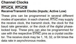 | |
| Posted by: Kai Robinson on 2020-08-15 00:16:09 Also - upon further signal inspection the 338-6523 is NOT likely to be a 6523 TPI as originally thought - the pins match up to the 6522 config instead, some obfuscation on Apple's part but would make the most sense since the 6522 is used in everything else, and there's nothing being used on what should be Port C, IRQ is connected to the other IRQ pins, R/W connected to R/W etc. I'd love to be able to edit my original post. At least that means one less custom chip to use - you can indeed use a brand new WDC 65C22N instead. | |
| Posted by: Kai Robinson on 2020-08-15 00:59:38 @cheesestraws @PowerMac_G4 - I HAVE DISCOVERED A TRACE ISSUE! Look here - you'll see i've connected stuff that has no business being connected. I accidentally pistook a trace going into a pad - turns out that i'd actually shoved the trace out the way while desoldering. I just verified against other SE boards - see the original, and the fix. Can cut the trace and patch direct with a bodge wire 🙂  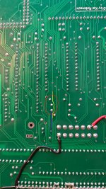 | |
| Posted by: Kai Robinson on 2020-08-15 01:00:38 Here's the patch around in the latest board rev. 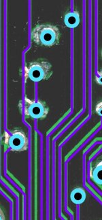 | |
| Posted by: Kai Robinson on 2020-08-15 02:22:12 ....aaand there's a short circuit between the power planes in all the board revisions. CANCEL YOUR BUILDS, DESOLDER. I'll send out another batch of boards 🙁 FFS - its only on the split power plane at the back - can't locate it...c8 links to gnd and power, and even without a capacitor in, the planes are linked. | |
| Posted by: Kai Robinson on 2020-08-15 05:23:43 However, some troubleshooting later (ie, desoldering all power from the rear I/O by removing the inductors...) IT'S (kinda) ALIIIIIVE!!!! 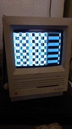 | |
| < 9 > |