68kMLA Classic Interface
This is a version of the 68kMLA forums for viewing on your favorite old mac. Visitors on modern platforms may prefer the main site.
| Click here to select a new forum. | |
| PowerBook 540c Restoration Project | |
| Posted by: 3lectr1cPPC on 2023-08-15 15:59:08 Ah, missed that. | |
Posted by: jmacz on 2023-08-15 16:34:10Well with tantalum caps the line indicates positive not negative, so you did that correctly, right? Yup, I did it correctly. But my question isn't about the negative marking on the electrolytics and the positive marking on tantalums. It's about the fact that on the board (as you can see from the pictures), there are clearly two caps that have the positive end connected to ground (even on the stock system). Given the stock caps were oriented this way both on my Sharp display as well as @croissantking's, I assume that's not a mistake. But I've been told that tantalums are not forgiving when they are inverted like this hence I'm asking for an expert opinion here from someone who understands more deeply the use cases where a polarized cap (stock) is inverted like this and whether it's safe to replace with a tantalum in this scenario. | |
| Posted by: cheesestraws on 2023-08-15 16:53:23 Don't forget that negative and positive are relative. Is the negative end of those capacitors attached to a negative supply that's even further negative than ground is? | |
| Posted by: croissantking on 2023-08-15 16:55:56 Somebody had a similar problem here: Powerbook 540c screen problemI got from a friend a powerbook 540c. He didn't know if it works because he hadn't power adapter and batteries. I bought a power adapter and two intelligent batteries which i connected them to the powerbook. I turned it on and it worked. It has Mac Os 8.1 installed and 36 mb ram. I left it...
There’s mention of a microfuse. | |
Posted by: jmacz on 2023-08-15 16:57:37Don't forget that negative and positive are relative. Is the negative end of those capacitors attached to a negative supply that's even further negative than ground is? I had not considered that. The positive end is going to chassis ground (where the negative end of the other caps are going). The negative end is going to a tiny daughterboard (in the picture) and into a circuit. I will get the caps back on and test to see what that negative end looks like. Somebody had a similar problem here: Hmm, I will look for that as well and test it to see if it's open. | |
| Posted by: jmacz on 2023-08-15 18:32:02 This circled component is the only thing that remotely looks like a fuse on the board, and it has continuity (it's not open) so I think it's fine? 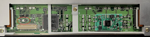 And here's the other side of this board: 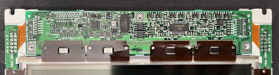 Nothing there that looks like a fuse (ie. I believe surface mounted micro fuses would look like a surface mounted capacitor but the center ceramic portion is white and/or the component is label F<something>). Nothing like that from what I can see on the bottom. Nothing like that on the bezel board either: 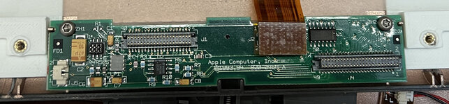 | |
| Posted by: jmacz on 2023-08-15 18:48:22 @3lectr1cPPC are the screens/ribbon cables direct replacements across the 500 series machines? like would the 540c screen work as a drop in on a 520c or would a 520 grayscale screen work in a 540c? I'm asking as I think someone I know might have either a 520 or a 520c so wondering if that might help me narrow down where the problem is (ie. a ribbon, a screen, the motherboard, etc). | |
| Posted by: jmacz on 2023-08-15 18:55:41 @croissantking for the electrolytics you used, did you specifically pick high frequency caps for the replacements or low frequency? | |
| Posted by: 3lectr1cPPC on 2023-08-15 19:23:22 No, the cables are all different from what I know. I’m 100% on the 520c/540c cables being different, not entirely sure on the grayscale ones but it’s likely there too. | |
Posted by: jmacz on 2023-08-15 19:29:34No, the cables are all different from what I know. Ah ok. That rules that out. Will continue pushing forward 🙂 | |
| Posted by: 3lectr1cPPC on 2023-08-15 19:39:23 Well, if anything, you are the single most dedicated person I've seen join this forum for a long time. If anyone deserves to figure this out, it's you! Keep on going and trying more things. It worked before, it should be able to be made to work again. | |
Posted by: croissantking on 2023-08-15 19:45:32@croissantking for the electrolytics you used, did you specifically pick high frequency caps for the replacements or low frequency? I didn’t pay any attention to this. I can look up which parts I used but they are likely just ‘general purpose’. Ah ok. That rules that out. Will continue pushing forward The bezel board and inverter are the same on my 520c as on my 540c, just FYI. | |
| Posted by: 3lectr1cPPC on 2023-08-15 19:46:52 Oh yes, I was thinking only of the cable for the LCD. Other cabling should be the same I'd think? Inverter is the same between models but that shouldn't have any impact with your symptoms. Not entirely sure about the cable from the base to the interconnect board but I'd assume they're the same between models. | |
| Posted by: croissantking on 2023-08-15 19:51:52 Here are some of the caps I used: These were quite nice Panasonic ones, but I did a bit of a pick and mix with some of the caps being generic ones off eBay, just because I had them in stock. You can see in my photos which were the Pannys. | |
| Posted by: jmacz on 2023-08-15 20:34:27 LOL, so ok, check this out. I didn't want to do this but this is all part of the debugging process. I put the OLD caps back on. I tested each one to ensure they were still showing a capacitance that was in spec. And then put them back on the board. And .... it works. The display works again and the powerbook boots without issue. So this is good, I know everything else is working. So I don't have more time today, but next opportunity I get, I'm going to replace the electrolytic caps one by one with a tantalum testing the display after each one to see if there either a bad tantalum (for whatever reason although all of them are in spec) or a particular cap location can't take a tantalum for some reason or it can't take any tantalums. This should be fun. 🙂 | |
| Posted by: 3lectr1cPPC on 2023-08-15 20:36:09 Haha no way! Lucky that you used a removal method that didn’t break the caps. Both hot air and the twist method usually do. | |
| Posted by: 3lectr1cPPC on 2023-08-15 20:37:34 That reminds me of a part of my PowerBook 100 repair. I was two caps short when first recapping the logic board, so I tested without them in place and the laptop worked but with no sound. So anyway, two caps come in and I install them. Computer stops working. I removed them, works again. Installed one of the two, works still. Installed the last, works still. Never figured out why it did that, but it shows that weird voodoo like this can happen. | |
Posted by: jmacz on 2023-08-15 21:05:44That reminds me of a part of my PowerBook 100 repair. I was two caps short when first recapping the logic board, so I tested without them in place and the laptop worked but with no sound. Haha. Yeah, so I guess I will be going through that process when I start replacing these with tantalums one by one. Lots of learning to be had here. I did use hot air. I put a ton of tin foil (and kapton tape to secure it) all over the areas around each cap as I was paranoid that the heat would damage the display. And then used the smallest tip I could find to heat the pin areas only (and used flux on the pins). Each one came off quick and were in good shape. I know the twist method is used but I was always paranoid that the pads might come off as you twist, so I don't do it that way. | |
Posted by: MacUp72 on 2023-08-16 00:10:45..But my question isn't about the negative marking on the electrolytics and the positive marking on tantalums. It's about the fact that on the board (as you can see from the pictures), there are clearly two caps that have the positive end connected to ground (even on the stock system). Given the stock caps were oriented this way both on my Sharp display as well as @croissantking's, I assume that's not a mistake. But I've been told that tantalums are not forgiving when they are inverted like this hence I'm asking for an expert opinion here from someone who understands more deeply the use cases where a polarized cap (stock) is inverted like this and whether it's safe to replace with a tantalum in this scenario. afaik this is not a mistake, this is DC not AC, so the caps do have a polarity , mainly used in smoothing out ripples in DC, in the circuit the signal does not change polarity. In an AC circuit capacitors are used in turning circuit in AC. These are non polarized, when the AC switches direction, it cannot damage the capacitors because the capacitor is simply not polarized and can be plugged in either direction. So true if you put an electrolytic capacitor (polarized) in an AC circuit, it will easily get damaged provided it exceeds it rating. | |
Posted by: croissantking on 2023-08-16 01:13:28I know the twist method is used but I was always paranoid that the pads might come off as you twist, so I don't do it that way.I employ this method and to date have not lifted a single pad. Now that I’ve said that I’ve probably jinxed myself 😂 | |
| < 6 > |