68kMLA Classic Interface
This is a version of the 68kMLA forums for viewing on your favorite old mac. Visitors on modern platforms may prefer the main site.
| Click here to select a new forum. | |
| PowerBook 540c Restoration Project | |
| Posted by: 3lectr1cPPC on 2023-08-13 19:41:31 I'd take it fully apart and check the ribbon cable for any tears. For instance, the speakers in the 5300 are much the same, where the data is being sent through the LCD cable. When I tore my 5300ce's LCD ribbon partially, I got only a blank white screen, but the backlight still came on and the speakers worked as it chimed. I'd look over all the cables very carefully for any damage. Just writing this to say that a chime out of the speakers doesn't mean the cables are fine. Motherboard shouldn't be an issue here as that one cap is just for battery charge I believe. The board should even work with it removed I'd imagine, but I can't confirm this. Just wouldn't charge any batteries. Oh, and thanks for posting those files! I'll link them on my website once I get around to updating all the 500 series pages. | |
| Posted by: jmacz on 2023-08-13 22:38:42 Argh, you are right. There looks to be a small tear affecting one strand on the ribbon between the bezel board and the inverter board. I swear I was super careful removing all the ribbons and storing them in a container. Not sure how this happened unless there was already a partial tear and handling it finally did it in. I will pull a wire from connector to connector just to see if it works once connectivity is restored. If so, will try my best to patch it somehow, otherwise, will have to look for a donor machine to pull one from. Someone is selling the ribbon on eBay but at that price I might as well look for a donor machine. | |
| Posted by: croissantking on 2023-08-14 01:47:10 Just to inspire you, here’s a repair I made to my 540c speaker cable after I accidentally tore it. 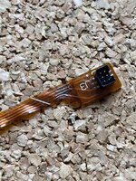 | |
Posted by: MacUp72 on 2023-08-14 05:59:30Just to inspire you, here’s a repair I made to my 540c speaker cable after I accidentally tore it. looks good.. I guess its the long cable inside the back chassis of the display..running around and getting bent once at the edge on top right? did you use tiny wires? 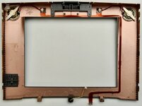 | |
Posted by: croissantking on 2023-08-14 06:29:50looks good..Yeah, that’s the one. It’s easy to forget to disconnect it when dis-assembling the screen. I used some 30AWG Kynar wire. | |
| Posted by: 3lectr1cPPC on 2023-08-14 07:28:10 Aw man... that really sucks. It's always the worst when that happens. Photo of the damage? Could be fixable. | |
| Posted by: jmacz on 2023-08-14 08:39:17 I think I should be able to fix it similar to what @croissantking did. It's 3 lines that are somewhat severed - if I flex the ribbon I gain continuity but normally it's disconnected. The damage looks like something like a screwdriver tip fell on it or something scraped it. Not quite sure what happened as it wasn't anywhere near anything pointy. 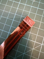 | |
| Posted by: jmacz on 2023-08-14 18:50:20 Repaired the break in the ribbon and have proper continuity on each end of the ribbon now. 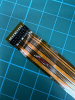 Tried it out and now the backlight comes on and the controls for brightness, etc work. But still having an issue. The screen now comes on but stays gray (no cursor, nothing else on screen) even though the OS has booted. Again, I know it's booting because I hear the "did not shut down properly" beep and if I click around with the mouse button I get beeps for each click until I hit the Return key on the keyboard to close the dialog and then clicking around doesn't give the beep anymore. But alas, the screen although lit shows just gray. The main display ribbon looks good and so does the main ribbon from the motherboard to the bezel. But will take a look at it more closely. | |
| Posted by: 3lectr1cPPC on 2023-08-14 19:18:15 Gotta be a flex cable issue I'd have to think. Keep scrutinizing, you'll probably find one. Great work on that repair too! | |
Posted by: jmacz on 2023-08-14 22:01:33Gotta be a flex cable issue I'd have to think. Keep scrutinizing, you'll probably find one. Great work on that repair too! Yeah, I would think.. However I've checked the remaining ribbons and they are both good. Checked all the pins both on both ends of the cable and also when attached by checking the points on the boards and it checks out. Looking at the LCD now and will be pulling the new caps one by one to test them again. | |
| Posted by: 3lectr1cPPC on 2023-08-14 22:02:22 Alright, good luck. Hope you find the issue! | |
Posted by: croissantking on 2023-08-15 04:00:37Yeah, I would think.. However I've checked the remaining ribbons and they are both good. Checked all the pins both on both ends of the cable and also when attached by checking the points on the boards and it checks out.Can you share photos of the recap job on the LCD? | |
Posted by: jmacz on 2023-08-15 07:14:35Can you share photos of the recap job on the LCD? I unfortunately don't have a photo ... the caps (tantalums) are off the board right now. I individually tested each one (off the board) and they are within spec. I reconfirmed they are at or above the voltage for the previous cap they are replacing, and the right capacitance. And given the polarity marking on tantalums are on the positive side, I ensured the orientation was correct as well for each. I did find this post from the forum from earlier this year, albeit for a PowerBook 100. But similar symptom where the backlist is powered on, the computer is alive and booting, but no image on the screen (related to recapping): I’ve recapped a whole bunch of PB100 recently and they all had the backlit blank screen issue. The first one which I recapped with tantalum caps still had the same symptom when I retested but weirdly worked perfectly the next day. But a few days later it started randomly doing it again. It is still unreliable. (original thread: https://68kmla.org/bb/index.php?threads/powerbook-100.43243/post-494056) @croissantking you and I have the same display (Sharp) and you went with electrolytics and had no issues right? | |
Posted by: croissantking on 2023-08-15 07:39:29you and I have the same display (Sharp) and you went with electrolytics and had no issues right?That’s right I have the Sharp and had no issues related to recapping, which I did with electrolytics. I’d be really surprised if the tantalums were the problem in this case, but you have nothing to lose by trying electrolytics. Have you checked the ribbon cables that go from the LCD driver board to the panel itself? Did you dissamble the panel in order to get access for soldering? | |
| Posted by: croissantking on 2023-08-15 07:42:11 These ones: 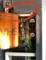 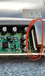 | |
| Posted by: jmacz on 2023-08-15 07:44:56 I did disassemble. And I checked those two ribbons particularly a few times now. I even continuity tested with the ribbons locked in and those are all good. | |
Posted by: croissantking on 2023-08-15 07:46:22I did disassemble. And I checked those two ribbons particularly a few times now. I even continuity tested with the ribbons locked in and those are all goodSounds like you’ve been thorough and careful in your work. | |
| Posted by: jmacz on 2023-08-15 15:00:14 I have a question for the electrical experts here. This is a picture of the original capacitors from my display (this is before I did any work on the caps). Note the polarity markings. The dark marking band is the negative side. And as you can see, it's pretty consistent (this is not important but I'm pointing it out so that it's easier to spot what I'm referring to in the second picture further below). 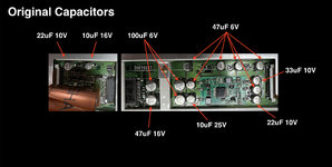 Now here's the board with the caps removed. You can see that there is a white outline on the board where the caps go and the shape of that outline has two angled corners which correspond with the positive side of the capacitor. This matches what I see in terms of the negative polarity markings on the original caps. So far so good. 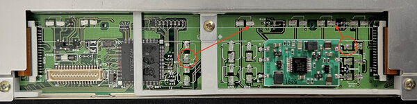 Now for my question. All the caps (EXCEPT two of them) have the negative side on ground. I've tested this with a multimeter. The huge expanse of green on the board is ground (as expected). But two of the caps, are inverted. I have circled the positive pad for these two caps and it's clear the positive side is on ground. The arrows also indicate how the positive pad is actually connected to the negative pads for the other caps. Given this, I'm trying to understand if this might cause an issue with tantalums vs electrolytic capacitors? I had thought with tantalums you never want to invert them. If someone could explain how this works that would be great. I want to learn. 🙂 | |
| Posted by: 3lectr1cPPC on 2023-08-15 15:57:28 Well with tantalum caps the line indicates positive not negative, so you did that correctly, right? | |
Posted by: croissantking on 2023-08-15 15:58:44Well with tantalum caps the line indicates positive not negative, so you did that correctly, right?I think they did: And given the polarity marking on tantalums are on the positive side, I ensured the orientation was correct as well for each. | |
| < 5 > |