68kMLA Classic Interface
This is a version of the 68kMLA forums for viewing on your favorite old mac. Visitors on modern platforms may prefer the main site.
| Click here to select a new forum. | |
| Getting G3 Whisper Perch USB working | |
| Posted by: Phipli on 2023-03-19 21:50:02 It won't work until you figure out what U9 is (as well as fitting the clock) because U9 is in line with the power to the port in your schematic. | |
Posted by: croissantking on 2023-03-20 01:28:42What's the component at F1?It’s a fuse off a FireWire card. Probably not the right rating, but I just put it in place temporarily. | |
Posted by: Phipli on 2023-03-20 01:32:55View attachment 53862I've just noticed you have caps fitted at R146, 147 and 148? These should be resistors? | |
Posted by: croissantking on 2023-03-20 01:34:18I've just noticed you have caps fitted at R146, 147 and 148? These should be resistors?Oops - you’re right. | |
Posted by: croissantking on 2023-03-20 01:52:27It won't work until you figure out what U9 is (as well as fitting the clock) because U9 is in line with the power to the port in your schematic.I’d argue U9 isn’t needed. See the attached photos from the CMD 0670 manual. They give three options for power connection. U9 might well be intended for the UCC 3912 it shows as option 3. It states to only use one option. So my thinking is that if I have the fuse onboard, I won’t need the chip. On my Whisper schematic, it looks like the 5v needed to supply bus power would come from VDD on the other side of the fuse. U9 is kinda separate from that circuit. If I were to integrate U9, I would omit the fuse and bus power would come from the chip itself along the same pathway. The Wings card doesn’t seem to have this chip as part of the footprint at all, although it does have the fuse and big capacitors, again backing up the idea that it’s optional. 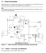 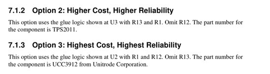 | |
Posted by: Phipli on 2023-03-20 01:56:19I’d argue U9 isn’t needed.Ah yes, the fuse isn't in line and has its own connection to Vdd. | |
| Posted by: croissantking on 2023-03-20 14:56:02 I’ve replaced the three wrongly fitted caps with resistors and added in an oscillator: 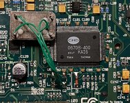 ASP now lists a USB bus: 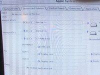 This is awesome progress. However, devices that are plugged in do not show any signs of life nor are they recognised. However a secondary 4 port PCI USB card now works again (5 buses are listed with it installed). A quick look at the USB log window shows a long list of events with reference to a ‘dead port’: 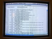 | |
| Posted by: Phipli on 2023-03-20 15:01:40 Gi en the error, I'd start by checking that pins 9, 10, 11, 22, 23 and 24 are set up correctly. Some of those pins are to do with verifying the correct voltages, if you don't have them wired in correctly, the chip will decide the supply isn't working and report a bad port. It's 3 pins per port. | |
Posted by: Phipli on 2023-03-20 15:04:26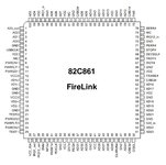 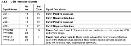 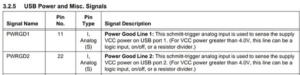 | |
| Posted by: Phipli on 2023-03-20 15:09:02 @croissantking how did you select the resistors for 146, 147 and 148? | |
Posted by: croissantking on 2023-03-20 15:12:10@croissantking how did you select the resistors for 146, 147 and 148?I thought that 10k ohms would be ok for pull up resistors, should I try something else? | |
| Posted by: croissantking on 2023-03-20 15:13:36 Also those resistors relate to the secondary USB port which does not exist on the footprint, therefore in reality maybe there is supposed to be a ‘dead port’ | |
| Posted by: Phipli on 2023-03-20 15:14:34 Just seeing what your decision process was. I think that's OK, but a couple more things. What is that clock sat on? Don't let it short anything. What is pin 11 connected to? Your schematic shows it unconnected, but I think it should be connected to something. | |
| Posted by: Phipli on 2023-03-20 15:21:00 You'll have to forgive me, I haven't looked at everything in detail so I'm trying to ask things about stuff that might be an issue, or I don't understand. I'm asking lots of dumb questions, but hopefully it is still useful 🙂 | |
Posted by: Phipli on 2023-03-20 15:23:27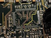 I dug out a card. Pin 11 goes that way. | |
| Posted by: Phipli on 2023-03-20 15:32:34 Did some more tracing. Looks like it goes to a potential divider between R75 and R76.  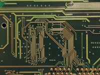 | |
Posted by: croissantking on 2023-03-20 15:34:04Did some more tracing. Looks like it goes to a potential divider between R75 and R76.It does. I just updated my schematic. I put 10k resistors on those, no idea if they're right. 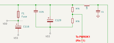 | |
Posted by: croissantking on 2023-03-20 15:36:51You'll have to forgive me, I haven't looked at everything in detail so I'm trying to ask things about stuff that might be an issue, or I don't understand. I'm asking lots of dumb questions, but hopefully it is still useful 🙂Yes, keep it up, with your input I'll get this solved 2x faster. Don't hold back! | |
Posted by: croissantking on 2023-03-20 15:38:56What is that clock sat on? Don't let it short anything.A square of 'nano tape'. It's not touching anything. I have the SMD part on order though. 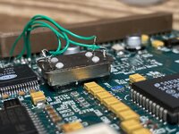 | |
Posted by: Phipli on 2023-03-20 15:39:43It does. I just updated my schematic. I put 10k resistors on those, no idea if they're right.Those won't be 10k and this would cause the issue you're seeing. That is a potential divider. Ideal would be to get values from another mac of similar age (sorry, but there is a gap in my collection, I don't have anything from the early G3 era after beige). If not... make R76 about 4 times bigger than | |
| < 5 > |