68kMLA Classic Interface
This is a version of the 68kMLA forums for viewing on your favorite old mac. Visitors on modern platforms may prefer the main site.
| Click here to select a new forum. | |
| Reverse Engineering the Macintosh LC III Logicboard | |
| Posted by: Trash80toHP_Mini on 2021-09-27 15:02:20 Looks magenta, that rocks! | |
| Posted by: demik on 2021-09-28 07:38:46 Good job, looks awesome. I swear thoses small pitched QFPs is what made humanity create BGAs 🙂 | |
| Posted by: mattsoft on 2021-09-28 08:21:58 A very royal LCIII! Looks awesome in purple! Really impressive all the reverse engineering that goes on in this hobby. Very cool stuff. | |
Posted by: max1zzz on 2021-09-28 14:29:26I swear thoses small pitched QFPs is what made humanity create BGAs 🙂Yep. I would take a BGA over a fine pitched QFP any day! The BGA is waaaay easier to solder 🙂 | |
| Posted by: mmu_man on 2021-09-28 15:46:00 Almost ashamed I successfully recapped my LC-III last year 😛 | |
| Posted by: max1zzz on 2021-10-02 03:20:49 A progress update: The board has now been populated enough for testing, and after finding and removing a short between /BERR and /HALT on the CPU the board now produces a slightly garbled chimes of death when powered on. This is good as if the board is working enough to produce a chime it must be mostly working! Just have to track down what's causing that chimes of death now.... | |
| Posted by: max1zzz on 2021-10-02 15:57:30 Annnd, We have floppy(icon)! 🙂 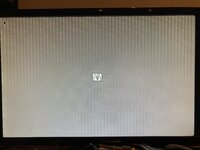 All the grief was caused by this:  That was causing a short between RA1 and RA2. Annoyingly because of the way sprint works this dose not show up as a error when you run DRC..... Audio still dosen't sound correct and is very quiet so it looks like there is a issue in the audio amp circuit, but at least it powers on and displays now! And a interesting tidbit about the LC III's architecture, It appears the system can instruct the clock chip to disable outputs. While troubleshooting I found there was no clock on the video DAC, a bit more poking revealed one of the clock outputs on the chip was missing, this lead me down a blind ally for a while thinking there was a issue in the clock circuit but it turns out the clock was there for about half a second, but was just being turned off as soon as the system crashed. This seems like a overly complex way to disable he video DAC but I guess it works! | |
| Posted by: Renegade on 2021-10-03 00:06:34 Great job max1zzz ! 🍾 | |
| Posted by: cheesestraws on 2021-10-03 03:22:59 Very well done! | |
| Posted by: joshc on 2021-10-03 06:28:53 Awesome work, well done! 👏 | |
| Posted by: mmu_man on 2021-10-03 07:41:41 YAY! | |
| Posted by: Trash80toHP_Mini on 2021-10-03 07:50:18 Nice find, great job. Did you drill out the shorted thruhole and patch wire the connections or cut traces and patch? If there were no bodges, it wouldn't look like a prototype! 😉 | |
Posted by: max1zzz on 2021-10-03 08:30:44Did you drill out the shorted thruhole and patch wire the connections or cut traces and patch?I cut the trace to either side of it and ran a bodge wire, I did consider drilling it but one side of that VIA is under one of the VRAM IC's which I didn't fancy desoldering! I also think I have the audio issues fixed, turns out I misread the value code on one of the resistors in the audio circuit and substituted a 2.2ohm resistor with a 2.8K one! swapping in the correct value fixed audio on the headphone socket, but the internal speaker was still too quiet, I had a hunch the headphone socket had bad switch contacts in it so i swapped it out for a new one which seems to have brought the volume of the internal speaker up to the correct level | |
| Posted by: max1zzz on 2021-10-04 12:18:10 Did a little bit more testing today, got the board to 7.1 from a scsi drive (after doing a little bit of shuffling around to get the correct system enabler on the HDD) 🙂 I also tried swapping the main oscillator crystal from a more commonly available 32Mhz crystal (The original being 31.3344Mhz) and the system seems to work just fine. I expect this results in a slight overclock of the system but I wouldn't expect any stability issues with this small of a clock difference (TattleTech reports a CPU clock of 24.96Mhz with both crystals but I suspect it isn't actually measuring the CPU clock.) | |
| Posted by: max1zzz on 2021-10-06 10:23:18 Finally got myself a proper oscilloscope, and can confirm the crystal on the LCIII is defiantly 31.3344mhhz: 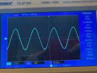 | |
| Posted by: max1zzz on 2021-10-09 14:14:41 Been doing some testing today: 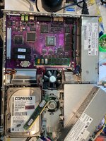 All good so far, only have ext scsi, Serial and sound in left to test. Also not what the best way to check the VRAM simm is working, the mac certainly isn't complaining about it but tattletech doesn't seem to be able to detect how much VRAM is in stalled... On a side note, dose anyone know of anywhere that has a stock of the 114pin din41612 connectors used for the 32bit PDS connector? I damaged the one off the doner board (and two of my other doner boards are badly battery bombed so will need new PDS slots) it's not the end of the world as 32bit PDS cards are rare but it would be nice to have a stock of them! | |
Posted by: cheesestraws on 2021-10-09 14:22:14Also not what the best way to check the VRAM simm is working See how many colours it'll let you select in the Monitors control panel? That PCB looks so stylish in purple... | |
Posted by: max1zzz on 2021-10-09 14:40:43See how many colours it'll let you select in the Monitors control panel?Ahh ok, I get thousands with the VRAM stick installed and only 256 without, so it must be working then 🙂 I know, can't decide if I'm doing the final boards in black of if I'll stick with purple.... | |
Posted by: cheesestraws on 2021-10-09 14:41:53Ahh ok, I get thousands with the VRAM stick installed and only 256 without, so it must be working then 🙂 That sounds like it's working, then! I know, can't decide if I'm doing the final boards in black of if I'll stick with purple.... Ooooh. Hard decision. | |
| Posted by: max1zzz on 2021-10-09 16:09:17 I did want to get the final boards made with a clear resist + enig finsh but the quote from PCBWay was about $330! I don't know I want them in that finish quite *that* much..... | |
| < 5 > |