68kMLA Classic Interface
This is a version of the 68kMLA forums for viewing on your favorite old mac. Visitors on modern platforms may prefer the main site.
| Click here to select a new forum. | |
| Reverse Engineering the Macintosh Plus PCB | |
| Posted by: ajacocks on 2022-01-22 15:49:30 @aeberbach did you see Adrian's video on getting video output from a Mac Classic, using the Pi-based RGB2HDMI? That might be an easy solution for the video out problem, without any new engineering. - Alex | |
| Posted by: Vasily_A on 2022-01-23 06:20:34 works great! I have been looking for a way to connect mac plus board to an LCD for a long time, but all methods except for this project did not give a good result without a lot of effort. I did not order a printed circuit board, for one piece with delivery it turns out to be long and expensive, in a couple of evenings I made it from what was found at home. milling adapter from XC9572XL VQ44 to pads with 1.27mm (1/20") pitch 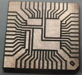 soldering the old CPLD dismantled from an unnecessary board ... 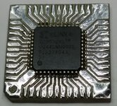 soldering on a breadboard in hamradio style: 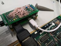 result: clicked the buttons, tuned in to the abnormal MAC PLUS output: HSYNC-Frequency 22.25kHz, 45µs period, 18.45µs low 59% PWM duty cycle VSYNC-Frequency (Refresh rate) 60.15Hz, 16700µs period, 180µs low 99% PWM duty cycle DATA 15.6672MHz, 512 pixels in roughly 32.8µs Signal has to be high while no pixels are sent and a stable image on a 19" monitor with HDMI input:  | |
Posted by: aeberbach on 2022-01-23 14:26:38@aeberbach did you see Adrian's video on getting video output from a Mac Classic, using the Pi-based RGB2HDMI?Sure, it works but it isn't Mac-like. If having lots of wires hanging out with an image on an external monitor is OK then that's been done by many people. The idea is for an image to appear on a LCD that fits in place of the CRT, case closed. No Linux, no menus, no boot delay. Even the brightness knob in the right place and functional. | |
Posted by: Mu0n on 2022-02-13 12:33:12works great!Nice work. I've successfully recreated Adrian Black's result on my Mac Classic 1, but I'm looking to repeat the deed on a Mac Plus. Do you mind showing me exactly where you intercept the hsync, vsync, video and GND on the Plus analog board? Did you need to add resistors to massage it into proper TTL? | |
Posted by: max1zzz on 2022-02-13 14:04:43Nice work.I'm not @Vasily_A but have done the same thing, I grabbed them straight off the Analogue board connector, no resistors or anything else needed The video signal is inverted in respect to the classics but there is no need to do anything about it as the RGB2HDMI can be told to interpret it as a inverted signal The only other thing I will add is I had no luck at all with the pre-set provided by Adrian, I remade a new config with the same settings and it worked fine so I have no idea what was up with it.... (I also tried his preset with a classic board and had the same issue) | |
| Posted by: Mu0n on 2022-02-13 14:14:09 His preset for a Classic was for an earlier version of the kernal for the project, it had confounded me for a bit but I ended up finding it after a while, iirc it's in the Sampling menu. I half remember that I had to actively turning sync on green from on to off (dunno if it was my mistake or not) and there's an extra parameter that came with the current day kernal versions that I had to fiddle with. | |
| Posted by: Stephen on 2022-02-13 14:41:11 Here's a screenshot of a walk through I posted elsewhere. 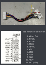 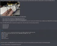 | |
Posted by: tevruden on 2022-02-13 16:43:44His preset for a Classic was for an earlier version of the kernal for the project, it had confounded me for a bit but I ended up finding it after a while, iirc it's in the Sampling menu. I half remember that I had to actively turning sync on green from on to off (dunno if it was my mistake or not) and there's an extra parameter that came with the current day kernal versions that I had to fiddle with. I can confirm this is the main issue, the Classic profile turns sync on green on and that needs to be turned off. | |
| Posted by: quorten on 2022-02-13 21:42:00 Interesting that there are revisions of the Plus boards that use the same TSM that was designed on 512k. I thought I mapped out the difference between the two TSM variants and it is relatively trivial... but I'd have to revisit. This is definitely the board I would need for testing the replacement RTC and PALs in hardware I've had out for a while... the feeling that a new board is expendible and replacable definitely helps encourage novices. Also, it might motivate me to offer replacement RTCs that I could say have been physically tested, which I figure would be seen as greater assurance than simply saying there is a firmware available that you can use to program your own ATTiny85. | |
| Posted by: buserror on 2022-02-14 01:38:14 Does anyone know if the logic board connector (male part) is easily available? I'm thinking of using the mobo with a RGB2HDMI and a +5V supply just by itself... AFAIK I don't need any 12V for the logic board (?) | |
Posted by: cheesestraws on 2022-02-14 02:12:12Does anyone know if the logic board connector (male part) is easily available? I'm thinking of using the mobo with a RGB2HDMI and a +5V supply just by itself... AFAIK I don't need any 12V for the logic board (?) The connector is, IIRC, just a Molex KK396 with a pin missing for keying (I can't check because I'm away from home but I'm 99% sure). Perfectly adequate clones are available on eBay. A suitably chunky pair of cutters or similar should deal with the extra pin well enough... | |
| Posted by: tevruden on 2022-02-15 17:49:55 Pin 2 is missing on the logic board. I know the SE motherboard needs +5V and +12V, but it's easily taken care of by an XL6019. I'll try to confirm its both +5V and +12V on the earlier motherboards but I also don't have access to the Plus logic board and I'm currently playing Find The Short on my 512K logic board. | |
| Posted by: cheesestraws on 2022-02-16 02:38:36 Per the schematics both -12 and +12 are used on the Plus LB, so you probably need all three to be present if you want the board to function fully. | |
| Posted by: max1zzz on 2022-02-16 06:44:57 -12 is only used for serial IIRC, The board will deffinatly boot without it present | |
| Posted by: cheesestraws on 2022-02-16 16:22:00 That would make sense 🙂. | |
| Posted by: tevruden on 2022-02-16 19:59:13 Yeah when I looked into this originally -5 and -12V are only used for serial. Supplying nothing but +5 and +12 and then using RGB2HDMI is feasible, though I won't call this outright success-- it's not flashing the icon, which means I'm probably not providing enough current and the CPU glitched: 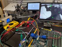 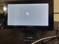 | |
| Posted by: buserror on 2022-02-17 03:07:23 Nice still, did you use a bench PSU or some other one? | |
Posted by: max1zzz on 2022-02-17 03:34:14it's not flashing the iconThat's just because the floppy drive is not hooked up, for some reason the icon doesn't flash on the plus without a drive present | |
Posted by: tevruden on 2022-02-23 23:11:51Interesting that there are revisions of the Plus boards that use the same TSM that was designed on 512k. I thought I mapped out the difference between the two TSM variants and it is relatively trivial... but I'd have to revisit. What makes it even worse, there seem to be different PAL sets. We couldn't figure out if the different revisions are interchangeable. Circling back to this: it does appear that the TSM is swappable between the Plus and the 512k at least in the trivial case. I've tested swapping just the 16R8 of the Plus for the 16R4 TSM from a 512k and it works to the point where you get the flashing disk icon. I haven't tested past that because this Plus motherboard really does not want to boot from a SCSI emulator. | |
Posted by: Trash80toHP_Mini on 2022-02-24 09:11:15I did not order a printed circuit board, for one piece with delivery it turns out to be long and expensive, in a couple of evenings I made it from what was found at home.LOVE it! I've got a few bundles of pad to DIP adapters form eBay on hand and have yet to use one. Your pink sea urchin rules! 😉 | |
| < 5 > |