68kMLA Classic Interface
This is a version of the 68kMLA forums for viewing on your favorite old mac. Visitors on modern platforms may prefer the main site.
| Click here to select a new forum. | |
| BGE's take on the Quadra 900/950 ATX PSU Mod | |
| Posted by: ktkm on 2020-07-27 17:22:08 I’m so close getting a Q950 right now -- this going to be indispensable! | |
| Posted by: BadGoldEagle on 2020-08-14 18:09:01 2000th post! Now I need to get a Radius Accelerator 16/25 in order to fit in this new 020 group! Before I write another 2000 and get the 040 status, let's take care and finish this Quadra project. The boards are done. Unless someone makes another suggestion... Changes since last post:
Speaking of relays, someone told me to only switch off and on the hot side (and not neutral), but I think it's actually a pretty bad idea to do that on a "universal" 120V/240V system. You see, nearly all power strips here have DPST switches, and for a reason. Some plugs in Europe are not polarized (CEE 7/3 type F), and although CEE 7/3 type E sockets should be earthed (and polarized), some really old ones still aren't and nothing stops you from plugging a device that needs a connection to earth into an unearthed socket (that's what I used to do back in the day, not my proudest moment, but the building was old and that was tolerated back then). The issue with unpolarized plugs is that you can plug your device either way. You've got a 50% chance of switching live and neutral around. It shouldn't be a problem since you basically have RCD (GFCI) on every plug in case the device has a problem. But if you're using a SPST relay, you may only be switching off and on the neutral side and not the hot side. And that's not great. Since the connections on the monitor plug depend on the input plug, a "wrong" connection on the input side will be spread to the monitor. The ATX PSU will tolerate but I'm not sure a 30 year old monitor will (and leaving it connected to live 24/7 is not recommended). So DPST it is. FYI, the Delta unit only had a SPST relay... Pictures! 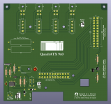 DC Board v0.97 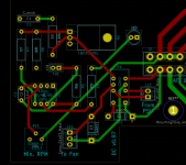 Close up (PCBnew view of the fan controller circuit) 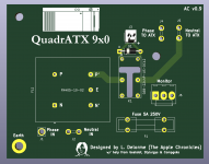 AC Board v0.9 I'll check the pad sizes once more before I send them to production. | |
| Posted by: Compgeke on 2020-08-30 01:41:24 Relevant to the thread, so I'll crosspost it here 🙂 Looks good! The only thing I want to confirm is those hard drive powers connectors are for you to plug in from the ATX PSU side, and then you use the 4 pin minifit to run to internal drives? | |
| Posted by: BadGoldEagle on 2020-08-30 02:30:02 Thanks Compgeke! those hard drive powers connectors are for you to plug in from the ATX PSU side, and then you use the 4 pin minifit to run to internal drives?And yes you are correct! On that note I think I'll just go ahead and order those boards. I've done enough quadrUPLE checks 😉 | |
| Posted by: archer174 on 2020-08-30 06:38:13 Looking forward to this! | |
| Posted by: BadGoldEagle on 2020-09-07 20:54:37 Look what arrived today! 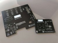 Initial multimeter tests show that there are no shorts, great! I kinda regret not using a different footprint for the Softpower transistor...oh well it's just going to be a tad more complicated to solder. Dimensions and screw holes look all right too! 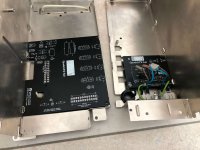 All the crimping and soldering will happen next Saturday. More to follow... | |
| Posted by: ktkm on 2020-09-07 21:03:29 Looking excellent! Can’t wait to see it installed and ready 🙂 | |
| Posted by: GeekDot on 2020-09-07 21:18:06 Like! :wub: | |
| Posted by: Renegade on 2020-09-07 21:49:21 Oops, wrong language. 🙂 I, too, am looking forward to seeing the result ! | |
| Posted by: BadGoldEagle on 2020-09-15 01:04:29 UPDATE: The DC board is ready! 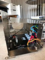 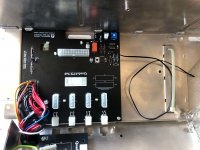 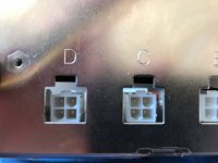 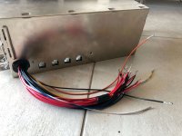 There are two small issues with it: 1/ The footprint for the Softpower transistor is a PITA. Thank Kicad for this. I should have used the 'universal' wide NPN footprint instead of the built in BC547 one... Unless you have pro equipment (which I don't), you'll bridge all three legs in a jiffy. It was nearly impossible to get the solder and the BJT out. I eventually did but RIPped one pad in the process. I was able to salvage board #000 by installing the transistor on the top and by bypassing the traces. Not the prettiest job I'll admit but at least it works. I will install the NPN myself before shipping the boards by routing the legs through the holes and underneath so that it won't be visible once everything is installed. 2/ The holes for the cable harness (J1) are slightly too small. They're big enough to let you install the 16 and 18AWG cables but it's a tight fit. The whole harness job is quite tedious and my fingers are still a bit sore from all that crimping. I am now thinking about getting one of these: https://www.corsair.com/us/en/Categories/Products/Accessories-|-Parts/PC-Components/Power-Supplies/Individually-Sleeved-24pin-ATX-Cable-Type-3-(Generation-2)%2C-BLACK/p/CP-8920053#tab-overview. It's not an extension cable, it's for a Corsair type 3 modular PSU: it goes from receptacle to receptacle, it's not a plug. It should be directly compatible (straight). Soldering the main 24 pin header to the board was rather easy so soldering another one in place of the harness should be a breeze. It would look less original, but black wires never look out of place. I haven't tested much as I couldn't get the cables out of the original 24 pin plug, therefore I have ordered a new one and will keep the original cable as some sort of trophy... but at least the PSU starts up when I short the blue and the white wires together (Key position:ON) and all the voltages are in the right place. It's a small victory in itself. While I wait for the plug to arrive, I'll test the fan circuitry and will solder the components onto the AC board. Also, I have been trying to calculate the LB power consumption... I'll probably create a new thread about this but here's where I'm at: QUADRA 900/950 Expansion cards According to Developer note -> 2x 25W + 3x15W (for 12V, -12V and 5V) According to Designing Cards and Drivers for the Macintosh Family 12V -> 0.175A and -12V -> 0.150A, beefed-up 5V power for Q900/950 unknown (2A per slot normally) => 20W (for 5 slots) for 12V/-12V total nubus=95W (2x25W + 3x15W) -> leaves 75W for 5V => 3A (5V, Q900/950) per slot => 15A total Hard drives 1A 5V x5 -> 5A total Motherboard estimation OG -> 33A-20A-> leaves 13A for the motherboard 25A ATX -> 25A-20A-> 5A motherboard (same as LC475 PSU for whole machine, apparently LC 020 and 030 machines have weaker PSUs) (*) QUADRA 700 (example) Expansion cards According to Developer note -> 3x15W (let's assume that PDS power consumption is similar) 13.9W (actual) per nubus slot -> rounded up to 15W in the documentation 3 (slots) x 2 (Amps, not high power unlike 900/950) =6A for 5V Hard drives 1A 5V x1 -> 1A total Motherboard estimation 15A PSU from PM7100 -> 15A-7A -> leaves 8A for the motherboard OG 12A PSU -> 12A-7A -> leaves 5A for the motherboard (same as QuadrATX 25A estimation above!!) In conclusion, since the Q700 was designed with the weaker PSU in mind, then the board may only get 5 of those 12A. Since a completely overloaded Q900/950 (*) is not something you see every day, and since its LB could still draw the same amount of power as a reasonably configured Q700 (much more common), then I would say that 'weaker' (25A 5V) ATX PSUs are probably just fine. The LC475/Q605s get less than 5A for the whole system! Of course I'll measure the actual LB consumption under heavy load without any HD/Nubus cards with an amp meter clamp once I get it up and running. temporary QuadrATX PSU LIST Best: Bicker BEA 630, 635 and 640 (5V@35A). Beware: H versions are weak! Seasonic RS650 (5V@35A) Good candidates: Seasonic industrial SS500ES 24A SS500ET/600ET 24A Seasonic consumer Eco Plus 600 24A S12II 520 (and up) 24A M12II EVO 620 24A X-650 25A Corsair RM550x (and up) 25A CX550M (and up) 25A TX650M (and up) 25A CX750M 25A VS550 (and up) 24A CS650M 25A VS600 24A CS750M 25A RM550 25A EVGA 650 GQ 24A 550 B5 24A Be Quiet! Dark Power Pro 10 650W 24A STRAIGHT POWER 11 550W 24A POWER ZONE 650W (and up) 25A Silverstone ST75F-P 25A ST70F-ESG 25A Bicker BEA 560 25A | |
| Posted by: BadGoldEagle on 2020-09-15 20:42:14 And here's a picture of the AC board. Almost finished, I have unfortunately ordered the wrong header for the monitor out plug... I'll have to solder that later. 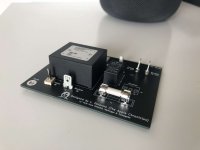 As far as the DC board is concerned, I'll test the fan controller this evening and I've already updated the footprint for the Softpower transistor. 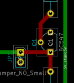 | |
| Posted by: ktkm on 2020-09-15 20:48:33 Really nice! What type of fuse are you using? Fast or slow? And also what is the value? | |
| Posted by: BadGoldEagle on 2020-09-15 20:53:05 I'm not a fuse expert, so I went with a 5A 250V 5x20 fast fuse. What do you think? https://www.arrow.com/en/products/bk-s500-5-r/eaton | |
| Posted by: ktkm on 2020-09-15 21:06:35 Sounds safe. I have an unrelated Issue with a refurbished IIsi PSU -- the fast 3.15A 250V fuse I switched to keeps failing. I was thinking of switching to a slow one just to rule things out. | |
| Posted by: BadGoldEagle on 2020-09-17 01:25:22 Small update: - Fan controller works. - The diode on the AC board should be reversed. The relay didn't work at first until I removed it. Not a big deal though. It's only silkscreen. Just place it backwards... | |
| Posted by: BadGoldEagle on 2020-09-21 17:01:09 Sorry for the lack of updates, the last puzzle piece (the 24 pin plug) is taking A WHILE to arrive. But I should have a functioning 950 by the end of the week! Edit: Also, I just bought my first vintage LCD monitor, a Fujitsu-Siemens X17-2 from 2003. Should work with the 950's internal video quite well. 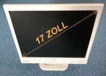 | |
| Posted by: BadGoldEagle on 2020-09-26 19:42:11 IT LIVES After months of hibernation, an elusive Quadra 950 emerges from its sleep. But there's still a small problem... Since most modern ATX PSUs regulate themselves based on what they see on the 12V rail, it is important to get it right. - Without the load resistors, the 12V rail was too high (12.5V). The PSU was clearly having issues with that rail and the ATX fan was on at full blast. - With some load resistors (2x 24Ohm 7W), the 12V rail sits at 12.25V (much better) and the fan is running at the lowest RPM setting BUT some smoke was coming out of the resistors… Not good! Turns out that was caused by a miscalculation on my part. It’s only by doing mistakes that you learn! Basically, I wanted to use two resistors in parallel and forgot to adjust the resistance. Explaination: The current draw depends on the resistance. A 24 Ohm resistor placed on the 12V rail will consume 0.5A (that’s what I aimed for as it’s the minimum load for the 12V rail according to the Bicker’s spec sheet). Power-wise this equals to 6W of dissipated heat. I chose a 7W (max capacity before blowing up or rating) resistor but the safety factor was too close to 1 (hence the smoking). Furthermore, I placed two side by side, thus drawing 12W or 1A. So I was drawing too much and the safety factor was too low. What I should have done: Since the resistors are in parallel, in order to draw the same power as one single resistor, you need to "double" the resistance rating (make the value larger ie decreasing the overall resistance of the resistor). So instead of 24 Ohm resistors, I went with some 47 Ohms. Each resistor will draw 0.25A (or thereabouts), two resistors (in parallel, which can be considered as two independent loads) will therefore draw about 0.5A. 250mA on a 12V rail corresponds to 3W (per resistor). So a 10W package should be able to dissipate that heat without too many issues. The display has arrived but I can’t do anything until I get the new resistors. I should get them in a couple of days. So testing will have to be delayed until next week. | |
| Posted by: ktkm on 2020-09-26 21:54:26 I can only imagine the satisfaction when you heard that first boot chime. I have my bicker 630 ordered now, can’t wait to put it good use. Good work! | |
| Posted by: BadGoldEagle on 2020-09-27 04:00:22 Indeed! I was pretty stoked to hear it wasn't dead after that last PSU explosion. And thankfully, nothing bad happened this time! I have my bicker 630 ordered nowNice! I still need to test the AC part (will do last, after the stress/endurance tests) but I might have bought enough to do a second set of AC cables (QuadrATX AC to PSU). Because we'll be using the same power supply, the cables will be identical. So I'll send you a set along with your boards if I have enough material to make them. | |
Posted by: ktkm on 2020-09-27 17:35:01Nice! I still need to test the AC part (will do last, after the stress/endurance tests) but I might have bought enough to do a second set of AC cables (QuadrATX AC to PSU). Because we'll be using the same power supply, the cables will be identical. So I'll send you a set along with your boards if I have enough material to make them.Sounds super! 🙂 | |
| < 5 > |