68kMLA Classic Interface
This is a version of the 68kMLA forums for viewing on your favorite old mac. Visitors on modern platforms may prefer the main site.
| Click here to select a new forum. | |
| Reverse Engineering the Macintosh LC III Logicboard | |
| Posted by: max1zzz on 2021-09-08 16:51:19 Copper areas are now done! 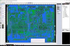 It doesn't look that much different, but it took ages to draw all those areas.... Next thing to do is the inner layers which are always fun! It;s amazing quite how much more apple packed onto that board compared with the LC, the LC has about 850 via's on the board whereas the LC III has over 1600! | |
| Posted by: ajacocks on 2021-09-08 22:49:28 Very cool. Appreciate all the hard work! - Alex | |
| Posted by: max1zzz on 2021-09-14 12:51:04 Annnnnd, I think we are done! 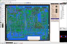 That took way longer than I expected, these boards are really densely packed! Time to send it to JLC 🙂 | |
| Posted by: chiptripper on 2021-09-16 00:22:28 Nicely done. The LC III was my first Mac. I've also somehow acquired oodles of orphaned LC III boards over the last year, so this project might be very personally relevant soon. | |
| Posted by: mmu_man on 2021-09-16 07:13:11 Amazing 🙂 | |
| Posted by: ronan on 2021-09-16 09:15:46 Naive question : are the Macintosh LC III chips easy to source ? I suppose that adb chips for instance are harder because apple specific but what about the others ? | |
Posted by: max1zzz on 2021-09-16 09:38:52Naive question : are the Macintosh LC III chips easy to source ? I suppose that adb chips for instance are harder because apple specific but what about the others ?Unfortunately not, the board uses a custom memory / system controller (The big chip in the centre of the board), a custom clock chip, custom DAC's for both video and sound and the custom ADB / rtc chip (Egret) The egret is in theory just a motorola microcontroller and I believe the code has been dumped form it, but sourcing that long obsolete chip or the equipment to program it is damn near impossible, I belive code compatible (but not pin compatible) chips are still made but as of yet no one has made a replacement. There is also a little 8 pin custom (or custom marked) chip that handles the switching between battery and mains power for the Egret and a couple of reset lines, there is a chip that is readily available from china in the same package, with a simmiler part number (that also looks like a apple part number) but until I get my order of those I don't know for sure if that is the right part (the part is marked 0120, the part form china is sold as 343S0120) Basically a doner board is needed to build one of these, thay are mainly intended for saveing battery damaged boards 🙂 | |
| Posted by: ronan on 2021-09-16 09:41:31 Thanks for your detailed answer 🙂 | |
Posted by: demik on 2021-09-16 15:28:25The egret is in theory just a motorola microcontroller and I believe the code has been dumped form it, but sourcing that long obsolete chip or the equipment to program it is damn near impossible, I belive code compatible (but not pin compatible) chips are still made but as of yet no one has made a replacement. IIRC, only the SE one (PIC based) has been dumped using a microscope, and one version of CUDA was dumped via a trick as well. Unfortunately, nobody managed to get either one running as far as I know. Anyway, nice work again ! I'm crossing finger for the first boot | |
Posted by: max1zzz on 2021-09-16 16:07:26IIRC, only the SE one (PIC based) has been dumped using a microscope, and one version of CUDA was dumped via a trick as well.I came across this a while back: https://www.gryphel.com/c/minivmac/extras/egretrom/index.html I haven't tried it to see if it works though | |
Posted by: demik on 2021-09-17 05:35:34I came across this a while back: https://www.gryphel.com/c/minivmac/extras/egretrom/index.html I haven't tried it to see if it works though Oh didn't know about this one. Added to the todo list. | |
| Posted by: olePigeon on 2021-09-17 08:09:00 Has anyone considered a "remix" board? Like taking a Q605 and changing its dimensions and port orientation so it'll fit into, say, an SE/30 or Macintosh Classic? | |
Posted by: kitsunesoba on 2021-09-23 14:11:30Has anyone considered a "remix" board? Like taking a Q605 and changing its dimensions and port orientation so it'll fit into, say, an SE/30 or Macintosh Classic?I'm curious about something similar, except the rework instead making the board fit a standard form factor, e.g. mini-ITX/micro-ATX/ATX so it can be placed in a commodity case. Sacrilegious maybe, but prudent with the cases of so many of these old Macs disintegrating due to aging plastic. | |
Posted by: max1zzz on 2021-09-23 14:51:51Has anyone considered a "remix" board? Like taking a Q605 and changing its dimensions and port orientation so it'll fit into, say, an SE/30 or Macintosh Classic?The mian issue there would be generating the correct signals to drive the CRT, however if replacing the CRT with something morden is a option is would be possible however the main issue is that making major changes to a board in sprint is not easy as sprint doesn't work like the PCB packages we are all used to now, it doesn't define connections so if you move anything there not easy to track what was connected to what I'm curious about something similar, except the rework instead making the board fit a standard form factor, e.g. mini-ITX/micro-ATX/ATX so it can be placed in a commodity case. Sacrilegious maybe, but prudent with the cases of so many of these old Macs disintegrating due to aging plastic.I'm sure someone suggested this earlier in the thread but I can't find that post now.... It's a very interesting idea and something I may look into in the future but has the same issue with making major changes to layouts done in sprint However there may be a solution! I am vaguely aware someone is working on a project to convert sprint layout files into KiCad layouts, this could potentially make modifications like this much easier! | |
| Posted by: olePigeon on 2021-09-23 17:54:57 @max1zzz Shouldn't be a problem. Someone's built a TTL to RGB adapter so you can put in custom TTL timings and output to HDMI. Adrian over at Adrian's Digital Basement successfully did it with a Macintosh Classic and other computers. I'm a bit excited about it because I believe it means you could theoretically replace a CRT with a 9" iPad screen. With that level of pixel density, you should have a crisp image with zero noticeable interpolation. That's all assuming you're OK with replacing the CRT with an LCD. | |
Posted by: Trash80toHP_Mini on 2021-09-24 18:15:18Has anyone considered a "remix" board? Like taking a Q605 and changing its dimensions and port orientation so it'll fit into, say, an SE/30 or Macintosh Classic?Too much custom Apple logic in the Q605 and not enough PCB real estate available in those form factors for that to be practical I'd think? What I'd like to see is someone working from the Portable's well documented LCD requirements backward to an 030 PDS frame buffer. At that point the SE/30 board could be reworked in the Portable form factor. We have design examples of cards for that machine to tweak to 640x400 for the flat panel and better for external monitor support. You'd wind up with an Apple IIc or Laser 128 A/c hookup required machine, but running tethered shouldn't be a major issue. Move to a current tech rechargeable battery setup and it might be able to run untethered? LCIII reworked into the Portable by the same means would be really cool, but wouldn't support the three interrupt capable external expansion/slot access provisions of the Portable's case that the SE/30 architecture offers. Native Video rework to 640x400 would be a major sticking point for that project as well. External connectors of any board would of course align with the Portable's backplane, especially the unused video connector. | |
| Posted by: max1zzz on 2021-09-27 14:04:09 Boards are here, and in JLCPCB's new and rather fetching purple! 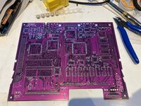 Soldering the PLCC's and SOJ's: 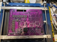 I did start trying to solder them by hand, but quickly remembered why I hate soldering PLCC's by hand and quickly went back to using a stencil and solder paste. It's just so much easier! And with the CPU and VLSI soldered: 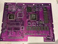 That VLSI chip is NOT fun to solder! is a 208 pin QFP with fine enough pitch that it's difficult to drag solder. Lots of flux and careful wicking was required. The more observant of you may notice something is not quite right with one of the chips, I need to fix that before I forget about it 🙂 | |
| Posted by: Bolle on 2021-09-27 14:17:12 Can’t tell where the pin 1 dot is on U1, but is it turned left by 90 degrees? | |
Posted by: max1zzz on 2021-09-27 14:18:07Can’t tell where the pin 1 dot is on U1, but is it turned left by 90 degrees?Yep, U1 should be rotated 90 degrees to the right | |
| Posted by: Bolle on 2021-09-27 14:26:34 Oh and yes, that purple looks awesome. Definitely will have to do a purple final run of some of my cards. | |
| < 4 > |