68kMLA Classic Interface
This is a version of the 68kMLA forums for viewing on your favorite old mac. Visitors on modern platforms may prefer the main site.
| Click here to select a new forum. | |
| Wombat (650, 800) board overclocking limitations | |
| Posted by: Nathan_A on 2021-08-06 23:04:18 I'm actually really surprised it gets so hot for not being an XC. | |
Posted by: trag on 2021-08-07 00:09:05Since I was running the Wombatris (IDK what I'm gonna call this) I propose: "WomBatman" | |
Posted by: cheesestraws on 2021-08-07 07:09:09it's like with each successive Quadra/Centris iteration, they kept consolidating chips into new ICs This is a general trend across computing at the time: Apple were doing it aggressively but they were far from the only ones. the SCC IC is present in the Wombat, as well as Quadra 700, IIci, and I'm not sure how far back The SCC family of ICs are used all the way back to the original Macintosh (and on the Lisa, too). When things got integrated onto fewer, larger ICs, it was still pretty much an SCC on that IC, it was just sharing silicon room with other cores. Geoport makes things more complicated, but you still have what boils down to being an SCC in there somewhere in the mess 🙂. | |
Posted by: cheesestraws on 2021-08-07 07:11:52I propose: "WomBatman" Presumably with the famous brass flourish as the startup chime? | |
Posted by: jessenator on 2021-08-07 08:24:04 | |
| Posted by: cy384 on 2021-08-09 20:48:49 Did a little more work on ultra-wombat-hax-tool, code and the new binary are on github (or download from my site). It interprets the bits and nicely prints a little more info. | |
Posted by: jessenator on 2021-08-10 12:16:56It interprets the bits and nicely prints a little more info.Nice! I'll have to grab that soon | |
Posted by: jessenator on 2021-08-12 09:49:24It interprets the bits and nicely prints a little more info.Nice work! so is all of this "digestible" text direct output from the djMEMC? even the parenthetical comments? e.g. "(ideal for 32 ish MHz)"  I set mine to be a Quadra 650 for the time being. I need to suss out which components can tolerate the overclocks, because with my initial trial with all of the oscillators I have didn't go as expected. I don't know if it's RAM, SCC, or otherwise. So I'd like to eliminate/check variables in a less haphazard manner, compared to what I've been doing, in my zeal : P Testing things on each Gestalt ID as suggested by @cheesestraws over IRC the other day, might be a more sensible approach. Although I wonder what willl happen at 35 or 59, when it 'expects' a different RAM speed… I guess we'll find out.  I do like that TechTool (1.2) does identify the Gestalts correctly. So here's my 'Quadra 650' per MacTest Pro (36):  or improvises on my 'unknown type' per MacTest Pro (51) 😀 :  | |
Posted by: cy384 on 2021-08-12 12:22:37so is all of this "digestible" text direct output from the djMEMC? even the parenthetical comments? e.g. "(ideal for 32 ish MHz)"all of the stuff it prints is read from the registers or reported by the OS, the "ideal for XX mhz" takes the number of cycles in the register and basically reverses the calculation described in the ROM comments (+/- rounding errors) there are like 6 different ways that the ROM seems to set the config register, so it prints the name from the ROM source if it matches one (e.g. "dj33Config") obviously some things will remain mysterious, like the meaning of the config register bit names, but it's nicer than just seeing the 1's and 0's | |
Posted by: trag on 2021-08-12 12:41:13I need to suss out which components can tolerate the overclocks I don't know if it matters, but it can't hurt to check what version of the MC88916DW is installed, -70 or -80. The -80 is supposedly a little faster. | |
Posted by: jessenator on 2021-08-12 14:07:25Check what version of the MC88916DW is installed. This is the one on the OE Centris 650 board where I'm testing:  This is the one on the OE Quadra 650 board I have:  Maybe I was too quick to write off @cy384 's suggestion that the on-board components have different specs… -_- my apologies. "ideal for XX mhz" takes the number of cycles in the register and basically reverses the calculation described in the ROM comments (+/- rounding errors)Gotcha. Well that will definitely be something to check against during the refined testing process. | |
Posted by: jessenator on 2021-08-12 14:51:10This is the one on the OE Centris 650 board where I'm testing: Well this is interesting… (from the datasheet, emphasis added) The MC88916 Clock Driver utilizes phase–locked loop technology to lock its low skew outputs’ frequency and phase onto an input reference clock. It is designed to provide clock distribution for CISC microprocessor or single processor RISC systems. The RST_IN/RST_OUT(LOCK) pins provide a processor reset function designed specifically for the MC68/EC/LC030/040 microprocessor family. The 88916 comes in two speed grades: 70 and 80MHz. These frequencies correspond to the 2X_Q maximum output frequency. The two grades should be ordered as the MC88916DW70 and MC88916DW80, respectively.I have a hunch of what this means, but can you shed some light, @trag ? It's also interesting that "55" (from my p/n) doesn't appear on this sheet… | |
Posted by: Nathan_A on 2021-08-12 19:53:08Well this is interesting… (from the datasheet, emphasis added)From what I can tell from my researching the chip (used on my Interware Booster30-33Fv2, though mine is a 70) is that it offers several output clock signals based on the input SYNC signal. Most of the output lines are clock doubled, but there's one "2Q_X" that is clock quadrupled from the input SYNC signal. So, the 55, 70, 80 part rating is indicating the max frequency of that quadrupled signal that the chip is binned to handle. So, if yours is rated at 55 Mhz, then that means if you intend to use the "2Q_X" output clock, then your max input SYNC signal is 13.75 Mhz. | |
| Posted by: trag on 2021-08-13 12:54:17 @jessenator Clock buffer chips are pretty common on computer systems. Imagine a bus with several different devices on it, which operates synchronously. I. e., they're all expected address/data phases at a particular time in a particular relationship. How do you give all those separate chips a concept of time like that? Obviously, you hook them all up to the same clock. But there are details. It turns out that the drive strength from a single oscillator isn't all that strong. And some chips need the signal doubled or halved for various logicy reasons. So, clock buffer chips. A single clock signal goes in. In theory everyone is running off that one signal. The buffer chip takes that one signal, and splits it into several identical signals which are all in phase with each other, to some very small tolerance and each of the chips on the bus gets its own clock from that buffer chip. Additional fancy things can happen on the buffer like dividing or multiplying the original clock for all or just some of the output clocks. Depends on the buffer chip and the system requirements. It sounds like some components on Wombat are using the straight system clock, but at least the CPU (?) needs a clock signal at twice the bus speed. Hence that 2Q_X signal. I haven't looked closely at the datasheet for the MC88916DW, and how WomBatman does things, but, for example, on the X500 Power Macintoshes, which have their CPU on a removable card, the clock signal also originates on that card. That way, the CPU card one installs controls the bus speed. But in practice, the way that is done is that six (6) different clock pins exit the CPU card and go out to components on the motherboard. Every CPU card for the X500 series has a clock buffer chip on board that splits the clock signal at least 7 ways (one extra for the CPU on the card). On the PPC601 chip, the chip does not have the ability to multiply its input clock, the way later PPC chips do, so if you have a bus speed of 33MHz, and you want the PPC601 to operate at 100MHz, then you need a clock buffer that can supply an X3 clock signal to the PPC601 chip. Anyway, I didn't realize that the datasheet for the MC88916DW doesn't cover the -55 version. I know it exists because I have a reel of five or 6 hundred of them here. I've been wondering what I can do with them, since they're the slow version. Not going to replace the fast version with the slow version. Do you feel comfortable replacing that chip? It would be interesting to do thorough speed testing on both machines and then replace the MC88916DWs with the -80 version and see if it makes any difference in the performance. I think I have some of the -80 on hand. I need to check, but if I do I could send you a couple. | |
| Posted by: Nathan_A on 2021-08-13 13:05:11 Here's the diagram from the datasheet that helped me make sense out of what's going on with the MC88916DW: 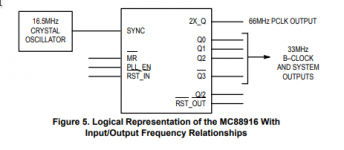 | |
Posted by: jessenator on 2021-08-13 14:21:22Additional fancy things can happen on the buffer like dividing or multiplying the original clock for all or just some of the output clocks. Depends on the buffer chip and the system requirements. It sounds like some components on Wombat are using the straight system clock, but at least the CPU (?) needs a clock signal at twice the bus speed. Hence that 2Q_X signal.Gotcha. So it sounds like the -55 value might could be a limiting factor on these Centris boards. I'm fairly certain an 800 will have a -70 part as well, but MrKSoft is going to check on theirs. Out of curiosity I just checked what's on the 840av board, and it's got an -80 part 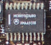 Thanks, Bruce for the high res image of the mobo I snapped this from! Thanks, Bruce for the high res image of the mobo I snapped this from!Do you feel comfortable replacing that chip? It would be interesting to do thorough speed testing on both machines and then replace the MC88916DWs with the -80 version and see if it makes any difference in the performance.I think I could. I've done some other 20 and 24 pin versions on a HD controller board, but I'll need to do some extra insulation on the nubus slot. Mine's not 'bad', but there's definitely some micro deformation on the end. This will be smack in the middle. With the MacClip on its way, adjusting clock input won't be as tedious. So yeah, I think it could be a hopeful avenue to test down. I've thought of first getting out the (native) Quadra 650 board and making it WomBatman, and then running the tests on it. The -70 part should be good up to 46.66 MHz — I have a shaky theory that 44 MHz is the narrow margin for the -55 p/n PLLs (which by math should have a 36.6666 MHz peak). As others who have converted their Centris boards to Quadras can stay level 44 Mhz with a 22.0000 input clock, there's some things I want to test first. I only have a 22.1184 crystal, and that may just be enough to cause problems. Here were my manual-resoldering-the-oscillator test results so far:  | |
| Posted by: LaPorta on 2021-08-13 14:35:50 Purely for my own edification: what exactly are you guys doing with these souped-up 44 MHz Quadras that you aren't doing at 25 MHz? | |
| Posted by: CC_333 on 2021-08-13 14:38:35 It looks like your board really doesn't like the OC refresh Frequency to be any higher than 597! Is it due to this: I only have a 22.1184 crystal, and that may just be enough to cause problems. Purely for my own edification: what exactly are you guys doing with these souped-up 44 MHz Quadras that you aren't doing at 25 MHz?I haven't the slightest clue, but my best guess would be that it's an exploration of potential overclock configurations that aren't possible with normal techniques, which don't account for the potentially beneficial changes in djMEMC timings which are activated by the unused gestalt IDs. c | |
Posted by: jessenator on 2021-08-13 17:41:53Purely for my own edification: what exactly are you guys doing with these souped-up 44 MHz Quadras that you aren't doing at 25 MHz?What are we doing with our vintage Macs that we can't do with FPGAs or software emulation? 🙃 For me, I'm doing it to see if there's an avenue of overclock that hasn't been tried, or some aspect that wasn't tested/known about. Maybe, maybe not. Pushing limits within reason. In parallel I'm hoping to learn more. Computing, programming, hardware design—this is how I do: immersion, deep diving. I know it's mildly insane, but here we are. 🤣 Paramount is my desire to do no harm to the board, of course. | |
| Posted by: Mr. Ksoft on 2021-08-14 17:46:26 Well guys, I have my results, and I'm going to confuse everyone possibly. My Quadra 800 has... the XC88916DW55. And yet, not only has it run happily at 44mhz... jessenator encouraged me to try some of the undocumented DIP switch settings on the MacClip and now the machine is running at 45mhz! (This seems to be the highest setting allowed using the MacClip). I didn't expect to see the -55 PLL in there... I feel like this throws a wrench in some theories, or I'm just lucky for now and this thing's going to blow up after a few hours 🙂 List all possible frequencies: Dip switches listed 0 for off, 1 for on, left to right: 1-2-3-4
I have not had time to test the system extensively at 45mhz, but networking, sound, video (both internal and NuBus) and serial MIDI all worked fine. Screenshot for proof: 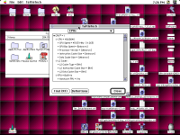 Also here's the ultra-wombat-hax-tool output: 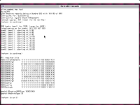 | |
| < 4 > |