68kMLA Classic Interface
This is a version of the 68kMLA forums for viewing on your favorite old mac. Visitors on modern platforms may prefer the main site.
| Click here to select a new forum. | |
| Twin PCI Riser Project for TAM, 6360, 5x00 Single Slot PowerMacs. | |
| Posted by: Trekintosh on 2025-02-21 19:50:00 Yeah I’ve got Illustrator, and it would probably be best to have those files so that we can be sure no measurements got wiggled in the conversion. | |
| Posted by: Trash80toHP_Mini on 2025-02-22 09:02:21 Excellent! Was just setting the Lombard back up to retrieve the development files. This'll be great, thanks so much for jumping into the fray! | |
| Posted by: Trash80toHP_Mini on 2025-02-23 07:26:48 My research notes are over on TD. TwiSlot PCI Riser and ComSlot2 NIC repro in widened CS riser form factorThe schematic for J8 of the 6500 says the reserved pins are for a PCI adapter card. I suppose the PCI adapter card is an Apple specific adapter so it can do weird stuff like requiring reserved pins to handle separate interrupts. The 6x00 two slot Riser is indeed specific to Alchemy/Gazelle and...
 tinkerdifferent.com
| |
| Posted by: Trash80toHP_Mini on 2025-02-24 09:11:33 Off today and tomorrow, so if you can note what info I have posted isn't clear enough and what you need in order of importance I'll start knocking things off that list. Need to pull the cardboard prototype and refine the AI8/PDF files. May want to set it back a skootch more if there's clearance at the rear? The RA cables are a bit too tight up against the backplane. Need to add Delta for Slot A to Slot B differentiation, I think I've assumed that in current illustrations, specific pinouts for Slot B needed? Dunno, anything you can think of would be good. If you can give me an idea of how schematics work in KiCAD I can give translation of my "Electron Plumbing Blueprints" into that form a try. | |
| Posted by: Trekintosh on 2025-02-24 16:04:26 Well, schematics are pretty simple. You place abstractions of the various components on the schematic, then draw lines between the pins. To make it tidier usually you run the pins into little tags called nets. They each have a unique name and just represent that all of said pins are tied together on the PCB. I’m happy to unplumb them for you, though. I’ll actually have some bandwidth this coming weekend now that I’ve picked up the 5400s and molar. Could you clarify what you mean by delta for slot B? | |
| Posted by: Trekintosh on 2025-02-27 14:58:06 @Trash80toHP_Mini *poke* just checking if you managed to get those illustrator files together | |
| Posted by: Trash80toHP_Mini on 2025-02-28 09:05:25 Been trying to get Slot_B clearly documented. You can probably figure the schematic out from This file, which I think is more akin to a KiCAD schematic than my plumbing: 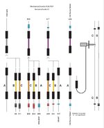 | |
| Posted by: Trekintosh on 2025-02-28 10:08:30 Hmm, I think I follow. Are the colored squares resistor values? If so, what values? | |
Posted by: Trash80toHP_Mini on 2025-02-28 14:38:05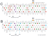 For R1 and R2 values I'll have to get back to you. It's somewhere in the threads, likely over on TD. Original sketch for MechanicalDoodle shows the resistive connection setup for Init Device Select clearly. Neglected to put that detail in the AI file. Resistive connection for Slot_A is made on Logic Board. For R1 and R2 values I'll have to get back to you. It's somewhere in the threads, likely over on TD. Original sketch for MechanicalDoodle shows the resistive connection setup for Init Device Select clearly. Neglected to put that detail in the AI file. Resistive connection for Slot_A is made on Logic Board.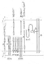 TwiSlot PCI Riser and ComSlot2 NIC repro in widened CS riser form factorThe schematic for J8 of the 6500 says the reserved pins are for a PCI adapter card. I suppose the PCI adapter card is an Apple specific adapter so it can do weird stuff like requiring reserved pins to handle separate interrupts. The 6x00 two slot Riser is indeed specific to Alchemy/Gazelle and...
tinkerdifferent.com
Mythical Slot C in the 6400 Alchemy Architecture & CSII Insanity@Androda got me entangled back into the web of CSII/PCI insanity with his amazing CSII 10/100 card project, so spinning off the tangent. Genesis of the Quest for the 3rd PCI Slot in the 6400 Alchemy architecture over at the MLA some six years ago: "In another thread, @trag mentioned that his...
tinkerdifferent.com
Haven't worked out what's going on the the two capacitors for each slot yet. My proof of concept test setup only had one slot connector on a ribbon cable based riser. All four iterations were the equivalent of Slot_A electrically, so no need for capacitors. I'll work that section out ASAP. | |
| Posted by: Trash80toHP_Mini on 2025-03-01 06:58:44 Spotted what might be confusing in the ancient Buzz-Lines-020-710 diagram and in the detail pic above. Resistive connections to Init Device Select of Slot_B and Slot_C are tied to address lines on the 1:1 connections of the address bus. Ignore the "tails" pointing down toward the Logic Board, they confuse the issue I think? Will correct for -800 series of drawings. Will be condensing info shown across the files linked above and others. Piecing together over five years worth of research/illustration here. 🤔 The three witness lines (boxes) somehow got filled in with black in the save as .PDF step. They'll open up in a second layer in AI for fill removal. I don't have specs on the relationship between Slot_A and the edge connector. Will put digital calipers on the 6360/5x00 single slot riser to determine that ASAP. Any more questions? | |
| Posted by: Trash80toHP_Mini on 2025-03-02 20:31:46 OK, it's Friday night in my world, so whilst partaking in adult beverages, I've pieced together the clearest diagram I can manage at this point: 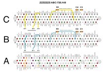 All connections from edge card to Slot_A are 1:1. Reserved pins of PCI spec hijacked for nefarious purposes by Apple for additional slots are indicated as are the Resistive Connections to address lines for Init Device Select of Slots B&C. I'll try to take a good look at the 6x00 riser to see how C1 and C2 are implemented tomorrow. If you can let me know what the reference points for locations of slots and edge connector will be in KiCAD I'll noodle that out as well. | |
| < 4 |