68kMLA Classic Interface
This is a version of the 68kMLA forums for viewing on your favorite old mac. Visitors on modern platforms may prefer the main site.
| Click here to select a new forum. | |
| Reverse Engineering the Macintosh SE PCB & Custom Chips for 1:1 reproduction | |
Posted by: SlickClick on 2021-01-08 12:36:22This shows the layer order.I didnt notice the active layers position thingy... Never used this app before... And Im only using the Viewer; not the full or demo, so its very limited... | |
Posted by: Scott Squires on 2021-01-09 11:49:47As for the schematic - oddly, tracing back the schematic is easier using the sprint layout, because you have the 'test pin' function - which shows all tracks connected to a pin, what goes to where etc. I took a peek at your Sprint Layout design. Very nice. Completely makes sense that this is a quicker and easier way to reproduce an existing design. Working smart! | |
| Posted by: Kai Robinson on 2021-01-12 10:59:40 @anthon - Thanks! It's still a WIP - still not sure what could be wrong at this stage, but i have my eye on the RESET circuit... @quorten, @asicsolutions - This might help you with the BBU - while categorising the ASIC Customs and making pinouts for them, i decided to do the BBU and colour code it all: https://docs.google.com/spreadsheets/d/1NDIA5orTwraRmOUgzrKxWYXcf2AXdULkdwUm020HdXI/edit#gid=1403563772 | |
| Posted by: maceffects on 2021-01-12 12:14:47 @Kai Robinson thank you for making this pinout map, it will prove to be helpful, I think. Still waiting on stuff to arrive from China to finish assembly, I'm hoping this weekend. | |
| Posted by: Kai Robinson on 2021-01-12 12:18:30 Thanks to the BOMARC Schematics - most of the pinouts are mapped for a lot of these ASICs, it's just a matter of tallying pin vs function, and the painstaking process of writing them down! | |
| Posted by: quorten on 2021-01-12 16:02:18 @Kai Robinson Interesting idea on setting up the layout of the data. Probably the circuit board footprint of the BBU's socket would be generally more useful when working with the hardware, though (of course not much different). I would recommend sticking to the Apple terminology that I've used in my bbu_pinout.csv pin listing because the Bomarc terminology isn't accurate for the RAM CAS pins on the SE logic board configurations. (If you read the fine print, that is.) | |
| Posted by: Kai Robinson on 2021-01-13 08:19:06 So to bypass the analogue board/psu issue and reduce the incident of electrocution, i have made my own PSU for the board tests out of a Meanwell RT-65, some 16-gauge wire, some spade terminals, ring terminals, a DPST switch and a 3-pin 1 amp plug 😀 Works first time! Although i maybe should have used 18-gauge wire, but squeezing them into the molex terminals was hard enough... So now all i need is an enclosure - open chassis aren't my favourite thing in the world. I also crimped a molex KK plug for a 64 ohm speaker, so i can have audio confirmation of beeps at startup 🙂 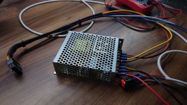 | |
| Posted by: quorten on 2021-01-13 13:50:04 How about something like the Walk-a-Mac? TTL-input video flat-panel displays are available under the names of "security monitor" or similar, then you just need a logic NOT chip to get the proper input video signals. | |
| Posted by: Kai Robinson on 2021-01-13 15:54:57 I've known about the TTL output for a while but...i thought the output signal would be useless for TFT's - do you have any more information? | |
| Posted by: quorten on 2021-01-13 17:35:52 The idea is to go for a flat-panel that caters to the traditional market served by PVM (Professional Video Monitor) CRTs, so you might search around for "security" or "industrial" monitors. Such displays have separate sync signals for RGB component video and are probably more forgiving to imperfect sync signals than consumer LCDs with VGA input. I thought that there might have existed some monitors that can take 5V signals directly, but in case that's not possible you could use voltage conversion circuits too. Here's one somewhat representative option I've found after much searching. https://web.archive.org/web/20150318133242/http://www.vartechsystems.com/techsheets/VT190WP2tech.html But the point is, if you break out some TTL video signals, it shouldn't be too much more trouble to connect that to something that can display it. | |
| Posted by: Kai Robinson on 2021-01-16 14:40:28 I think i have the answer!!!! /AS was cross connected to A8 on the PDS Slot -(anyone with the sprint layout file can check this) one track intersected a little too close - should be possible to cut the trace and patch it around - but this looks promising - i was wondering why there was no activity on any of the buses! I'll try this fix in the morning - but for now the missus is groaning at me to turn the lights off and come to bed...and we all know that happy wife = happy life 😀 | |
Posted by: joshc on 2021-01-16 18:07:59but this looks promisingFingers crossed! but for now the missus is groaning at me to turn the lights off and come to bedDoesn't she know that history is being made here? or...dug up... anyway, you get my point 🙂 Very excited about this project, let's hope you are as close as you think you are. | |
| Posted by: maceffects on 2021-01-16 19:40:37 Sounds very promising indeed! Please keep us posted. I’ll eventually buy some because I figure it’s high time I build an entire computer from nothing but raw materials... Well maybe not from silicon directly... | |
| Posted by: timdorez on 2021-01-17 08:42:08 Hey guys ! I wanted to thank everyone of you who contribute to this project. I have been following it since the beginning and wanted to say a little something. I have no real diagnosing skills but I know how to solder quite well and have lots of compact Macintosh (I have something like 50+ Macintosh) so that may be useful, who knows. Also, I'm from the North of France so not so far away from you @Kai Robinson. 😉 I was wondering, has anyone thought about reproducing the strengthening bar ? This is quite important as well I think. Maybe would you have some leads on how to have it manufactured @maceffects ? | |
| Posted by: timdorez on 2021-01-17 09:22:25 Here is a scan of some technical data I've got. It is a low-quality PDF to reduce upload time but I can send the 600ppi version if needed. Those are pages taken out of a Macintosh SE Apple Service binder I have. They are in French but nothing too complicated I hope. 🙂 Have you guys ever heard about the AppleCAT ? Those are similar to the TechStep and help you test a Macintosh with another one or run self-tests as well if the machine's working. I own two so I can have a go at testing a board with it if it can help. 🙂 View attachment SE Technical data.pdf | |
| Posted by: Kai Robinson on 2021-01-17 10:45:33 Right so today has been interesting... First thing i checked was the BBU and the ROMs from my board, using a spare board that @cheesestraws sent me a few weeks back - they checked out - even the mac classic BBU was tested as working - so yes, confirmed, the Classic BBU is identical to the SE's, in functionality and pinout. Then i bridged the /AS to A8 bridge and voila - bus traffic appeared! However that was about the size of it - no magic beep, still. Then i looked at the 74F257 spot...err...oops. I'd only tacked in the DIP sockets, and not connected the rest 😀 So, with those soldered on correctly, i checked everything again. AARGH! /AS looked like the resonance cascade at Black Mesa! Oh, wait, forgot to connect the ground clip again...! The reset line looks like this:  Note the 124Khz cycle time - that's 124 clock cycles. As per the 68000 manual: "The RESET instruction causes the processor to assert RESET for 124 clock periods toreset the external devices of the system." However, it's stuck in a loop, just staying active for 124ms, then resetting and trying again. Let's check the CPU clock:  Looks A-OK to me. This is using the cloned GLU chip by Porchy, rather than the original, too. So let's look at the composite video signal now...  Yep - 22KHz signal, looks to be a checkerboard, from the sync signals. Hmm. So, let's start checking address lines:  Looks stable enough to me...now how about the data lines?   What in the...? Okay - some are nearly dead, with no activity, some are like this, with some sort of macabre rollercoaster going on - and yes, i did double check the probe grounds, this time round! I swapped BBU's, swapped VIA's, swapped the Clone GLU for the original GLU, swapped the SWIM out for the Harris one i received the other day (works fine btw), even swapped the68000 itself, back to the gold version, and no change there, either...i've got some reaaaaally f'ed up signals on the 74FCT245's, and swapping those out made no difference either. The 74F257's were also swapped out, but pin 12 of U2E seems to produce garbage, even when i can see the incoming signal is A-OK...perhaps a faulty batch of F257's? Thoughts and comments, idea's etc? | |
Posted by: Kai Robinson on 2021-01-17 10:48:18Here is a scan of some technical data I've got. It is a low-quality PDF to reduce upload time but I can send the 600ppi version if needed. Bonjour Tim! Ca va? J'habite en Bretagne pour douze ans, pres de St. Malo 😀 Those PDF's are GREAT! The schematics are especially valuable - do you have schematics of the whole system? @quorten has been vectorizing the only existing page of the schematics, and page 2/3 would be invaluable! 😱 Many Thanks, Kai | |
| Posted by: timdorez on 2021-01-17 11:24:06 I'm fine, thanks ! I hope everyone's fine as well. 🙂 Unfortunately, those are the only schematics they chose to include. I would have loved more of them as well. :/ Here they are in 600ppi @quorten. View attachment SE Schematics.pdf | |
| Posted by: macdoogie on 2021-01-17 13:10:36 Are you saying that you see what should be the checker board pattern on the video signal? That should suggest that the processor did quite a bit of running and managed to fill the frame buffer with the checkerboard gray background pattern... | |
| Posted by: History_SE30_Dude on 2021-01-17 14:37:59 Came across these at Excess Solutions in San Jose lots of SIM sockets especially 30 pin. The only angled ones however are plastic clips. I figured anyone rebuilding a SE might be interested in these. 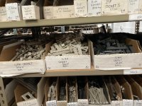 | |
| < 31 > |