68kMLA Classic Interface
This is a version of the 68kMLA forums for viewing on your favorite old mac. Visitors on modern platforms may prefer the main site.
| Click here to select a new forum. | |
| Macintosh SE/30 Schematics (modernization effort) | |
Posted by: elemenoh on 2020-04-27 11:29:07This is so cool! It is far easier to read than the originals! How hard was it to make this page? It would be really useful to have a complete set.Thanks! It took maybe 6-8 hours over several days. The others should be faster now that I've learned the tool. Yes, KiCAD can create a PCB design that's connected with the schematics. But I suspect recreating the board layout would take a substantial amount of time and effort. Anyone here want to help me with the other sheets and/or PCB layout? | |
Posted by: davidg5678 on 2020-04-27 11:41:11Anyone here want to help me with the other sheets and/or PCB layout?I'd be happy to try creating another one of the sheets, although I'm a bit unsure of my KiCad skills. I knew how to use EAGLE a few years ago, but I am out of practice at this point. I suppose this would be a pretty fun way to relearn how to make schematics. | |
| Posted by: Bolle on 2020-04-28 10:24:51 Be aware that the Apple schematics are not correct in at least one place so be sure to compare everything to the Bomarc schematics as well. I forget where that was though but pretty sure it was in the video section. | |
| Posted by: elemenoh on 2020-04-28 10:46:35 @BolleThanks for the tip. I'll do a comparison and update the file accordingly. | |
| Posted by: elemenoh on 2020-05-14 11:39:08 I've updated the video interface and finished the CPU/FPU page. New link to a folder where I'll add the others: https://drive.google.com/drive/folders/10VO6n72vsn52xqMyOgSZpi11tbyv7_Yx They're still just PDFs, but when I figure out how to properly redact, I'll share the KiCAD files too. They're really helpful for highlighting a path between pins! | |
| Posted by: Torbar on 2020-05-14 11:54:55 The folder says to request access, not sure if you intended it that way or if you meant to make it publicly viewable | |
Posted by: elemenoh on 2020-05-14 12:10:23The folder says to request access, not sure if you intended it that way or if you meant to make it publicly viewableI've just updated the link above to a version that should be properly shared. | |
Posted by: Torbar on 2020-05-14 12:44:47I've just updated the link above to a version that should be properly shared.Looks good now, thanks! | |
| Posted by: elemenoh on 2020-05-15 15:36:50 Added another sheet and cleaned up more stuff on the others. All three should be in good shape now. What do these asterisks (or are they bullets?) on the sheet labels mean? Inversion? 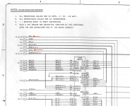 | |
| Posted by: elemenoh on 2020-05-18 19:19:25 I've finished! A complete PDF as well as individual pages is available here: https://drive.google.com/drive/folders/10VO6n72vsn52xqMyOgSZpi11tbyv7_Yx I tried to keep the drawings as close as possible to their originals, but some modifications were unavoidable. There are some labels that might be wrong due to fuzzy characters and my lack of knowledge about some components. For example I couldn't tell if a label was "PU" or "PV". Please let me know if you have any corrections. Also, I think I figured out a way to export the KiCAD files and will share those as soon as possible too. | |
| Posted by: Trash80toHP_Mini on 2020-05-18 21:47:04 Fabulous! What's next, a sexy new Socketed BLACK Logic Board for populating with components from lost cause acid burned donors? [🙂] | |
Posted by: joshc on 2020-05-18 21:54:49Fabulous! What's next, a sexy new Socketed BLACK Logic Board for populating with components from lost cause acid burned donors? [🙂]If someone was able to do that, I would happily buy several... | |
| Posted by: Torbar on 2020-05-19 14:25:08 Those look fantastic! I've been needing to pull out my SE/30 to diagnose an issue with the floppy controller, and this is going to help a ton vs the old schematics. | |
| Posted by: techknight on 2020-05-20 09:44:45 If your going through the effort of doing the schematics in KiCAD, you might as well layout a new PCB to replace bad ones. | |
| Posted by: elemenoh on 2020-05-20 09:57:22 I have no EE background and couldn't read a schematic a couple months ago let alone make one. I don't think I want to deal with the learning curve to make a layout for the PCB. My goal was to copy the Apple schematics as closely as possible so that they'd be easier to read during troubleshooting. As a result, the files don't follow some KiCAD conventions like wiring connections, sheet connections etc. Also, I had to make a ton of custom components, but didn't bother with making footprints for them. I'll be posting the KiCAD files soon. If someone else wants to create the layout, that'd be awesome. It would be cool to have another means of saving SE/30s. And even more importantly it'd be great to have a PCB in a custom color! 😉 All that being said, I have been thinking of some enhancements for the schematic. Let me know if you have other suggestions. 1) Pin orientation for ICs like those in the BOMARC drawings 2) A special sheet to make it easier to check all of the video related mux and address lines | |
| Posted by: Trash80toHP_Mini on 2020-05-20 16:17:32 Somebody needs to take this on! While we're at it, there's no need to slavishly recreate it in stock form: RAM needs to be upgraded to take a quartet of 32MB or a pair of 64MB 72pin SIMMs, I've done much of the legwork on another project: | |
| Posted by: elemenoh on 2020-05-20 16:33:27 I've added some pin maps to the first page. Let me know if these are good or if the style needs tweaking. If they're good, I'll add them to the rest of the pages. 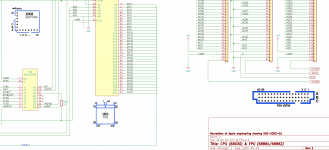 | |
| Posted by: elemenoh on 2020-05-20 19:11:06 I ended up adding them all. Still open to feedback about them though. | |
| Posted by: joshc on 2020-05-20 20:49:54 Where's @maceffects and his engineer friend when you need him... ;-D With my limited understanding of this from a technical level, I can acknowledge this would be a pretty hefty undertaking. Creating a board like this was much easier for Apple because they'd done it before with other machines, and had lots of skill and knowledge already in the company, as well as access to other resources and money. It would be interesting to see what could be done with a partial redesign. The Classic II logic board fits a 68030 into a board half the size, though with other limitations. As with all these projects, scope is important but so is having the resources, namely money, time and knowledge. I for one, would happily contribute to a kickstarter for such a project - unfortunately I wouldn't be able to assist much more than that. | |
| Posted by: elemenoh on 2020-05-20 21:35:44 I've corrected a couple labeling errors and added a cheat sheet at the end showing all the pins for each component connecting to each address line. Let me know if you have ideas about how to better arrange it. 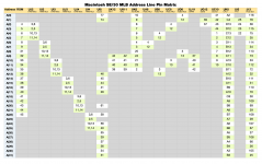 | |
| < 3 > |