68kMLA Classic Interface
This is a version of the 68kMLA forums for viewing on your favorite old mac. Visitors on modern platforms may prefer the main site.
| Click here to select a new forum. | |
| Micron Xceed SE/306-48 and SE/30 issue | |
| Posted by: zigzagjoe on 2024-08-01 12:07:04 Leave the micron on for a moment and check if any chips get hot on the micron... that is a lot of voltage drop even with the stock harness. | |
| Posted by: croissantking on 2024-08-01 12:13:35 Nothing really. A couple of GALs get slightly warm, but nothing more than the the PALs on the main logic board. | |
| Posted by: croissantking on 2024-08-01 19:08:28 Did the /HALT signal help you understand things better? | |
| Posted by: zigzagjoe on 2024-08-01 19:48:54 Yes, the card is continuously signalling the 68030 to retry the current bus cycle. Never exits; so it's essentially hung. Not immediately obvious what would cause the card to signal a retry; the manual doesn't reference it. May be worth validating that both crystals on the card are still working: 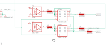 Your logic analyzer won't be fast enough to capture these properly, but you should get a square wave of some sort just with an incorrect frequency. Probably pin 9 and pin 18 of U23 would be best ones to check | |
| Posted by: croissantking on 2024-08-02 06:36:37 Would it be better to use a multimeter to check the frequency? Mine does have a mode for this. | |
Posted by: zigzagjoe on 2024-08-02 06:48:24Would it be better to use a multimeter to check the frequency? Mine does have a mode for this. Usually multimeter frequency measurement is meant for KHz range at most, it likely won't work. A scope would be the ideal tool to look at it, but the LA should be enough to confirm that something is there rather than nothing at all. | |
| Posted by: croissantking on 2024-08-02 12:06:00 Pin 18's output looks wrong to me. Zoomed in view:  Zoomed out view: 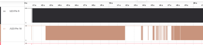 | |
| Posted by: croissantking on 2024-08-02 12:30:03 My multimeter does correctly display the 30.24Mhz signal on pin 9. Pin 18 which I guess should be 27MHz shows 0.00Hz. So, a bad oscillator at Y1 maybe? 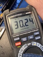 | |
| Posted by: croissantking on 2024-08-02 12:44:25 Both oscillators' outputs produce a nice looking square wave, so if pin 18 definitely should be putting out 27.00MHz then U23 must be bad. | |
| Posted by: croissantking on 2024-08-02 12:59:12 Here's another funny thing. If I gently brush against pin 11 (with one of the leads of my multimeter) on U23, the machine sometimes gets unstuck and boots up. Tattletech doesn't see the card. | |
| Posted by: zigzagjoe on 2024-08-02 13:38:10 That's definitely an interesting result. If you want to do a quick and dirty test, bridge pin 2 to pin 4 on U23 and see if anything changes. U23 is simply a buffer, so this should do nothing as the output should agree with the input signal, less a smidge of propagation delay. But if the output driver is not behaving correctly, this might cause it to do something different (ie. boot further). Also impressed your meter can read that frequency! | |
Posted by: nyef on 2024-08-02 15:18:58Both oscillators' outputs produce a nice looking square wave, so if pin 18 definitely should be putting out 27.00MHz then U23 must be bad.No, pins 9 and 18 are mutually-exclusive tri-state outputs. One of them will always be high-z if the other is driving, and vice versa. Either manipulate the FREQADJ signal or probe at pins 2 and 11 for the inputs. If 9 is showing a clock then 3, 5, and 7 should all show the same clock. If 18 is showing a clock then 12, 14, and 16 should all show the same clock. Also note that 3 and 12, 5 and 14, and 7 and 16 are wired together, so you should see the same active clock on both sides. | |
Posted by: croissantking on 2024-08-02 17:01:57No, pins 9 and 18 are mutually-exclusive tri-state outputs. One of them will always be high-z if the other is driving, and vice versa. Either manipulate the FREQADJ signal or probe at pins 2 and 11 for the inputs. Right, ok. So my captures above look alright to you? This may be a false lead then. I think the contact with pin 11 sometimes unfreezing the machine and allowing it to boot is a clue, however. | |
Posted by: zigzagjoe on 2024-08-02 17:19:43No, pins 9 and 18 are mutually-exclusive tri-state outputs. One of them will always be high-z if the other is driving, and vice versa. Either manipulate the FREQADJ signal or probe at pins 2 and 11 for the inputs. If 9 is showing a clock then 3, 5, and 7 should all show the same clock. If 18 is showing a clock then 12, 14, and 16 should all show the same clock. Also note that 3 and 12, 5 and 14, and 7 and 16 are wired together, so you should see the same active clock on both sides.Whups. Good catch: I didn't actually look at the logic there, just where a clock could be expected. And yes, I'd concur that touching it (ie. adding a bit of capacitance/resistance/possibly a weak pull up or down) causing different behavior is very interesting and worth digging into. | |
| Posted by: croissantking on 2024-08-02 18:22:15 What does the IRE jumper do on the card? There are two positions, labelled 0.0 and 7.5. | |
Posted by: zigzagjoe on 2024-08-02 18:28:32What does the IRE jumper do on the card? There are two positions, labelled 0.0 and 7.5.Black level of output signal IIRC. It should be described in the tech docs. | |
Posted by: nyef on 2024-08-02 19:16:49Black level of output signal IIRC. It should be described in the tech docs.Sounds right. NTSC black level is 7.5 IRE, NTSC-J black level is 0.0 IRE. Hence why some people recommend setting a US TV brightness to 7.5 if using an old Japanese game console over composite or RF. Presumably some other display standards have a similar variation. | |
| Posted by: croissantking on 2024-08-03 08:01:25 I actually socketed the 74F241N chip yesterday. Just to see what would happen, I booted up without the chip installed and the symptoms are the same. Interestingly, the contact with pin 11 of the socket still seems to unfreeze the machine sometimes. That pin goes back to the output of one of the crystal oscillators through an inductor and is not connected to anything else. Curious. | |
| Posted by: r6velocity on 2024-09-10 08:55:37 Hello, I have been following this thread as I also have a Micron XCeed 306-48 that does not work. Thread is here: https://68kmla.org/bb/index.php?threads/help-with-se-30-and-micron-xceed-se-306-48.35568/post-543462 If my card turns out to be unfixable, maybe it would be useful for parts. | |
| Posted by: croissantking on 2025-03-14 10:50:10 Been fiddling with this card again, now that I have my Hakko FR-301 I've been able to easily socket most of the chips. I've discovered that if I remove either U42 (address decoder) or U38 (bus cycle control) the SE/30 will start up. Yes, the card is continuously signalling the 68030 to retry the current bus cycle. Never exits; so it's essentially hung. Not immediately obvious what would cause the card to signal a retry; the manual doesn't reference it.Validating this statement, I can get a start up if I lift both the /BERR and /HALT pins on U38, and Tattletech sees the card too. I'd quite like to try replacments for those two GALs to see if one of them is malfunctioning. Since we have the equations in the technical handbook, would something like EQN2JED produce a valid Jedec file that I can use to flash a new chip? | |
| < 3 > |