68kMLA Classic Interface
This is a version of the 68kMLA forums for viewing on your favorite old mac. Visitors on modern platforms may prefer the main site.
| Click here to select a new forum. | |
| PowerBook 1400c/166 restoration/combination thread | |
| Posted by: 3lectr1cPPC on 2023-07-15 20:51:26 Bottom half of the main unit is now pretty much completely assembled for good! Tested it and all’s working well. FDD, PCMCIA, Sound, Keyboard, Trackpad, all good. The top halves are going to take until the end of next week I reckon though. Progress though! | |
| Posted by: 3lectr1cPPC on 2023-07-15 21:46:46 It just gets stranger and stranger. I just extracted a paper clip from the secondary 1400 that had somehow come lodged under the logic board sometime long ago. What on earth??? 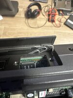 | |
| Posted by: 3lectr1cPPC on 2023-07-15 22:00:26 The secondary unit is also now mostly assembled and it too works. The untested touchpad module works alright. Slightly more sensitive than the one in my main, so slightly wonky, but perfectly usable. Now to wait until tomorrow evening on that first LCD housing part. | |
| Posted by: 3lectr1cPPC on 2023-07-16 10:19:04 Well it has been going too good so far I suppose 🙁 Recapped LCD is sad. That daughter board with the two ribbon cables is not screwed in in this clip, when it was I was just getting the horizontal stripes you see when I press on it. Reseated the two ribbons and no change. Any ideas as to what’s up? If I’m down an LCD than my secondary unit won’t work. View attachment trim.58135F56-037A-4C33-8A64-520AE229425D.MOV | |
| Posted by: 3lectr1cPPC on 2023-07-16 10:25:55 View attachment trim.831E258B-2E0D-4430-A81E-E906261B1402.MOVFixed! One of the ribbons appeared connected but at a closer look wasn’t properly. | |
| Posted by: 3lectr1cPPC on 2023-07-16 10:54:15 It’s been well over 24 hours, I think it’s time to reassemble the 3D printed reinforced display housing and test it. Hasn’t been a full 48, but it looks and feels completely solid, and JB only says it takes 24 hours and we’re a solid 36 in. I just installed the threaded inserts with a soldering iron - all in fine. 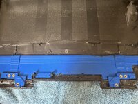 | |
| Posted by: 3lectr1cPPC on 2023-07-16 11:33:28 Well this is incredibly frustrating and disappointing. It appears there is a major misalignment in the part. 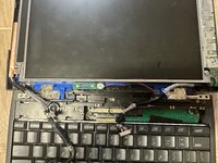 The only thing that I can imagine would have caused this would be an error during the printing process at the place I had these parts made. The part is perfectly aligned with the case, and the inserts are also perfect. I have no clue whatsoever what else could have caused this to happen. Now I really don’t know what to do 🙁 | |
Posted by: 3lectr1cPPC on 2023-07-16 13:08:22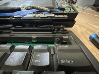 Comparing with the stock panel, the right hinge is the misaligned one. Definitely going to chop the other hinge fix in half to prevent this from happening. For this one, I’m going to be risky and attempt to melt the right standoffs to the left slightly. May work. If that fails, I’ll use the cracked panel on the secondary. | |
| Posted by: 3lectr1cPPC on 2023-07-16 14:23:37 I think this can still work! I’ve carefully melted the right side inserts to the left a bit and it’s now *so* close to fitting. Just a tad bit more and I think I’ve saved it! 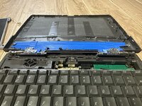 | |
| Posted by: 3lectr1cPPC on 2023-07-16 15:06:44 Uuugh, almost. It does screw in now, but it’s so tight and just slightly off, and there’s an ominous bend I don’t much like. One more adjustment and I think I may be good. 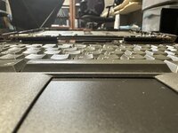 | |
| Posted by: 3lectr1cPPC on 2023-07-16 15:58:24 It’s done. And yes, I was basically working continuously on it since my first post where I talked about a plan for a fix to the misalignment. This took absolutely forever and is potentially the most difficult repair job I’ve done, ever. At the very least it’s up there. Now to reassemble the screen and test the hinge. 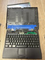 The left side ended up being misaligned as well by the way… | |
| Posted by: 3lectr1cPPC on 2023-07-16 16:42:27 Reassembled and working. 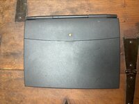 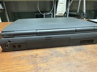 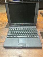 And the hinge works! Did make a big ol’ crack sound once but nothing looks broke so something probably just popped back into place or something. I also did away with the rear metal shield because it was so bent and likely pointless with the new reinforcement. I’m somewhat unconvinced however that this will prevent cracking. The left side had a tiny crack before I started, and it still appears to disappear when I apply upward force on the front of the display, indicating it’s still being flexed. I suppose we’ll see. Compare photo 1 where the crack is visible to photo 2 where I’m applying upward force. 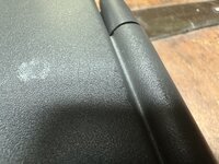 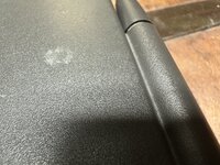 I’m don’t for the night though. Tomorrow I’ll start on the main 166MHz unit’s display housing, trying to prevent the mess I caused with this one. | |
| Posted by: croissantking on 2023-07-16 18:35:05 I’ve just recapped my 1400c, too. I used Polymer caps, so they won’t leak. 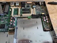 | |
| Posted by: 3lectr1cPPC on 2023-07-16 18:40:13 Say, how did you get your solder joints looking so nice? Even with lots of flux mine just didn't melt well... probably time I get a better iron? Eh. the current one does get the job done. It does fine when there aren't giant ground planes. | |
Posted by: croissantking on 2023-07-16 18:46:05Say, how did you get your solder joints looking so nice? Even with lots of flux mine just didn't melt well... probably time I get a better iron? Eh. the current one does get the job done. It does fine when there aren't giant ground planes.Lots of practice, I guess, though I didn’t find it any more challenging than any other recap I’ve done. Maybe your iron isn’t hot enough. Are you using leaded solder? Flux really does wonders, usually. When I have trouble with ground planes wicking away heat, as I recently did on a PC ATX motherboard recap, I’ll get out the hot air station and assist the soldering iron with a bit of additional heat. | |
| Posted by: 3lectr1cPPC on 2023-07-16 18:51:18 I guess my iron isn’t hot enough when doing these giant ground plane things, only explanation I can think of really. Also the tip I used is very fine but I sort of had to to fit everything. My soldering usually comes out much better - here’s a photo of my PowerBook 100’s board 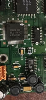 I have my iron around setting 4/5 (it doesn’t do a temp readout) already though usually. | |
Posted by: croissantking on 2023-07-16 18:54:20I guess my iron isn’t hot enough when doing these giant ground plane things, only explanation I can think of really. Also the tip I used is very fine but I sort of had to to fit everything. My soldering usually comes out much better - here’s a photo of my PowerBook 100’s boardIt could be that your tip is too small, maybe? Bigger ones do deliver more heat. | |
| Posted by: 3lectr1cPPC on 2023-07-16 18:55:36 The one I was using almost certainly is - I just was concerned about space. Probably could have made the larger one work though, that small one really isn't great. | |
Posted by: croissantking on 2023-07-16 18:58:58Working!Did you know you can downclock it to 133MHz and it’ll work? | |
| Posted by: 3lectr1cPPC on 2023-07-16 19:01:50 Interesting, I did not! Well I've got a 166 board so I'm good for now, but that is good to know. Do you know where I could find resources on downclocking? Would be a good page for my website. I wonder why it doesn't work at 166 though, Newer, Sonnet, Interware, etc, managed to get G3s working on the 117/133 boards no problem. Would love to know the technical explanation behind that if anyone does know. | |
| < 3 > |