68kMLA Classic Interface
This is a version of the 68kMLA forums for viewing on your favorite old mac. Visitors on modern platforms may prefer the main site.
| Click here to select a new forum. | |
| Reverse Engineering the Macintosh LC III Logicboard | |
| Posted by: mmu_man on 2021-08-31 04:52:42 LOL! Possibly they later on patched the layout to bypass them but manufacturing still had the pick&place configured to put them. Next time I open mine I should check if they're here. What part of the circuit are they on? | |
| Posted by: max1zzz on 2021-08-31 14:59:27 they are connected to pin 24 of the ext SCSI connector and pin 4 of the serial ports to ground, after this I found C40 (again by the serial ports) and C70 (Above the PDS connector) are the same. These look like they are linking the audio / IO ground planes to the normal ground plane, I guess apple orignally did this with caps then changed the design at a later date | |
| Posted by: 360alaska on 2021-08-31 15:49:34 This? | |
Posted by: cheesestraws on 2021-08-31 15:53:18This? But wouldn't you want to not assist high-frequency stuff from getting from the digital ground to the analogue ground, as that's the point of having two grounds? Or am I missing something? | |
| Posted by: 360alaska on 2021-08-31 19:14:05 If you read the thread: This is actually common when dealing with EMC. The zero ohm resistor has some parasitic inductance, so the capacitor acts like a better path to ground at high frequencies. Many designs will have options for a few different ground coupling layouts and then test to work out what they need to achieve compliance. | |
| Posted by: cheesestraws on 2021-09-01 02:44:16 I did read the thread! What I don't understand is why coupling high frequencies effectively between the grounds is a good thing in this specific case. I'm being stupid rather than illiterate 🙂. It's not meant as a passive-aggressive swipe, you may well be right, but I'd really like someone to explain to me why, because grounding is black magic and I don't understand it. | |
| Posted by: max1zzz on 2021-09-01 14:10:01 Traces more or less done on both sides: 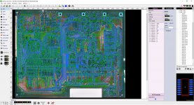 Still have copper areas to do, But i'm getting there! | |
| Posted by: mmu_man on 2021-09-02 09:24:07 Are you just doing the PCB directly or the schematics also? Could be interesting to be able to patch it. At least to add a switch/jumper for overclocking 🙂 | |
| Posted by: max1zzz on 2021-09-02 09:34:34 I'm just doing the PCB, BOMARC schematics are already available for this model I have been considering drawing up schematics for the LC though from my board layout, as no schematics are available for that one | |
| Posted by: mmu_man on 2021-09-02 12:28:16 Well, schematics available as ugly bitmap scans and schematics in a usable format is different but yeah… | |
| Posted by: max1zzz on 2021-09-02 12:31:29 The BOMARC schematics are modern scans and are 100% readable, I see no reason to re-engineer the wheel here. The apple SE, SE/30 and PLUS schematics floating around the place are a different matter though. | |
| Posted by: mmu_man on 2021-09-02 13:30:54 Yeah but modifying the PCB without the schematics would be harder without at least a netlist for checks. | |
Posted by: Trash80toHP_Mini on 2021-09-04 19:21:00Well, schematics available as ugly bitmap scans and schematics in a usable format is different but yeah…max is doing three boards at once, that's above and beyond in my book. Check out the Bomarc schematics as he suggested, translating those into schematic capture format for PCB design apps would be a great contribution to the overall effort. | |
Posted by: mmu_man on 2021-09-06 13:37:16max is doing three boards at once, that's above and beyond in my book. Check out the Bomarc schematics as he suggested, translating those into schematic capture format for PCB design apps would be a great contribution to the overall effort.Well I would maybe if I didn't have so many projects already. And then I'd do it in KiCAD anyway so it probably wouldn't match with the PCB which would be a shame. | |
Posted by: mogs on 2021-09-06 17:06:20What I don't understand is why coupling high frequencies effectively between the grounds is a good thing in this specific case. The designers get to choose exactly how these two grounds are bonded, maintaining control over the flow of return currents at all frequencies. Otherwise you're leaving it to chance how high frequency return currents make their way back to the power supply. I've actually experienced this problem on a board I worked on, the designer used two ground planes bonded with inductors (they said to prevent high frequency coupling). This resulted in significant and measurable noise on the second plane. I ended up just bridging them together with solder and the noise went away. A capacitor might have achieved a similar result. At the end of the day I don't think the designer was right to do that without providing an alternate path for the high frequency return current. It's also pretty common to place capacitors to bridge slots and notches in ground planes, to prevent high frequency return currents flowing around the slot (which has a tendency to emit RF). | |
Posted by: cheesestraws on 2021-09-07 00:56:22I've actually experienced this problem on a board I worked on, the designer used two ground planes bonded with inductors (they said to prevent high frequency coupling). This resulted in significant and measurable noise on the second plane. I ended up just bridging them together with solder and the noise went away Thanks, this explanation was really helpful. One of these days I might understand this stuff... | |
| Posted by: CC_333 on 2021-09-08 12:34:02 @max1zzz How is this project progressing? c | |
| Posted by: max1zzz on 2021-09-08 12:42:26 It's getting there slowly, I have almost finished the copper areas on the top and bottom after that I only need to do inner planes and board outline. Should be ready to send to production in a week or two 🙂 | |
| Posted by: CC_333 on 2021-09-08 12:46:21 Ah, OK! You haven't been saying much about it lately. I figured you were still working on it quietly, but I was curious about your progress. If you're up for it, I eventually wouldn't mind a clone of the backlit Mac Portable logic board made. I even have a broken donor for you to analyze, if so desired! c | |
| Posted by: max1zzz on 2021-09-08 16:11:48 Indeed, I have spent the last week or two just drawing little coloured boxes on the board so not much to report! Ohh that would be intresting! Do you know if the backlit portable's board is compatible with the non backlit's chassis? I only have a non-backlit portable so testing would have to be done with that | |
| < 3 > |