68kMLA Classic Interface
This is a version of the 68kMLA forums for viewing on your favorite old mac. Visitors on modern platforms may prefer the main site.
| Click here to select a new forum. | |
| Reverse Engineering the Macintosh SE PCB & Custom Chips for 1:1 reproduction | |
| Posted by: Kai Robinson on 2020-07-06 05:35:25 The end result so far is this... I'm about 25% done with the power planes so far, but i still need to tweak the solder masks around the back panel area, and the cutouts. 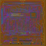 View attachment macse7.JPG | |
| Posted by: Kai Robinson on 2020-07-06 05:37:55 Oh and if anyone wants some angled 30-pin simm headers, try here: https://www.peconnectors.com/sockets-pga-cpu-and-memory/ | |
| Posted by: joshc on 2020-07-07 05:55:07 Firstly, awesome project, the vintage Mac community is in some dire need of this sort of thing compared to the Amiga community which already has a lot of reproduction boards ready to buy. Secondly, that is possibly the most exploded PRAM battery I've ever seen - that looks scary to touch or even go near. | |
| Posted by: Kai Robinson on 2020-07-08 06:51:59 OK - just a small one today - the silkscreen has been done for 80% of the board now, with component values (as much as i can find) ready to make a BOM. I've basically got the SIMM sockets and the PDS slot left, and a few resistors. I've tweaked the metal reinforcing points to proper solder pads, too. I've also managed to properly split the power planes for rear I/O isolation through the inductors 🙂 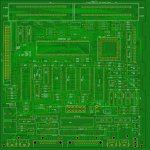 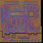 | |
| Posted by: Kai Robinson on 2020-07-09 07:53:00 AAAAAND DONE! Literally every last pin checked, every component given a proper value (so i can export a BOM), all ground and power planes checked, even against the 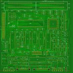 | |
| Posted by: krishnadraws on 2020-07-09 08:06:08 This is really cool! I love the idea of a new logic board for our vintage machines. Sorry about the Maxell bomb on the SE. That's probably the most scary damage I've seen it cause. (And this is coming from someone who bought a Mac SE/30 with a Maxell bomb "surprise"). | |
| Posted by: IlikeTech on 2020-07-09 08:06:39 Soldering one of these together sounds like a lot of fun! My SE board works, but I wouldn't mind putting one together to test! | |
| Posted by: cheesestraws on 2020-07-09 08:14:09 This would be fun. I am very likely interested. | |
| Posted by: max1zzz on 2020-07-09 08:22:09 Very nicely done! I would be interested if only I had a SE to test it in... | |
| Posted by: Kai Robinson on 2020-07-09 19:12:09 JLCPCB now has the order, estimating 1 week til delivery - I have 2 boards out of that batch to spare, so - who here has an SE with battery damage, or one they can pull the customs out of, to test this recreation? | |
| Posted by: Kai Robinson on 2020-07-09 20:13:04 BOM Attached - the only value i cannot find, is R48 - so if anyone can find it (it's the resistor below J12, the main connector), please let me know! View attachment MacintoshSE BOM.txt | |
| Posted by: LaPorta on 2020-07-09 21:35:17 I have enough spare board/parts to probably put together a working one of these. We would have to build a parts list for all those odds and ends that we don't really know what the heck are (or, in my case, have no training to know what they are). Have you nailed down how much one would cost? | |
| Posted by: Kai Robinson on 2020-07-09 22:14:29 Well, most passives are about £30 roughly guesstimating - refer to post 1 to see what you should salvage or have to buy new. You can get 338-6523's (they're just Rockwell branded MOS/CSG 6523 TPI's) for about £5 each, the 26LS chips are £2, the other logic is anywhere from £1.20 to £3 depending on vendor. SIMM sockets can be salvaged, but i recommend buying new from the link i posted on page 2. | |
| Posted by: cheesestraws on 2020-07-09 22:18:53 I am both up for this and in the UK (I gathered from your spelling of 'arse' in the first post you might be over this way, and the £s confirm it), if that makes shipping of boards easier? I have a dead SE board that has suffered a mild battery explosion and I think all the chips ought to be salvageable. | |
| Posted by: Kai Robinson on 2020-07-09 22:21:34 @cheesestraws OK - DM me your address, i'll post one out when it arrives. It's FoC as it's a prototype board 🙂 | |
| Posted by: cheesestraws on 2020-07-09 22:51:25 Oh, and: the only value i cannot find, is R48 Here's a photo of that area on my board, though my main connector is labelled J11 (do we have a different board revision?) 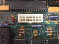 If my eyes do not deceive me, that's 3.3k? | |
| Posted by: Kai Robinson on 2020-07-09 23:22:28 J11 is aux battery header. J12 is the main connector - look under the silkscreen for the 53C80 SCSI chip, you should see it. However, you're quite right, that *IS* a 3.3k! Which makes sense, since all the other pullups are rated for that, too. | |
Posted by: cheesestraws on 2020-07-09 23:51:23J11 is aux battery header. J12 is the main connector - look under the silkscreen for the 53C80 SCSI chip, you should see itYou're quite right, apparently I just can't read. Ta 🙂 | |
Posted by: CC_333 on 2020-07-11 15:31:11J11 is aux battery headerActually, I'm 99.8% sure that's for the speaker? This is a very incredible project! If anyone ever does one for the SE/30 (probably much more ambitious, but technically not much harder than this, I'd suppose? At least better schematics exist for it?), I'd consider giving one a try, as I have several boards which, if I haven't sold them all, I could salvage custom chips off of. If there were a way to do it non-destructively (there probably is), I suppose one could even "borrow" the custom chips from a working board as well for testing purposes, yes? c | |
| Posted by: Kai Robinson on 2020-07-11 19:08:04 Well I can do the board - but i need one desoldered completely. it's possible to buzz via's etc for ground or +5v connections, so you dont need to sand a board, but using a few dead boards is a better plan than wrecking a working one. Plus i only need to salvage certain chips like the 26LS and anything Apple custom. For all testers of this initial batch - i forgot the GND and +5v connections for the disk and serial - DOH! For some reason i skipped over them, it's fixed in the latest Gerbers, but the prototype batch will need these connecting - nothing major, just solder bodge wires and bridge pins for the SCSI - should see from these images where the GND and +5 connections are - light brown is +5v, dark brown is GND. 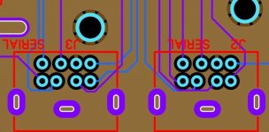 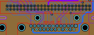 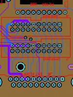 | |
| < 3 > |