68kMLA Classic Interface
This is a version of the 68kMLA forums for viewing on your favorite old mac. Visitors on modern platforms may prefer the main site.
| Click here to select a new forum. | |
| Macintosh 128k issues | |
| Posted by: Ferrix97 on 2016-09-23 15:30:43 I'll try right now (it's 00:30 in the morning here, and I'm half asleep), Hopefully I won't fry it | |
| Posted by: techknight on 2016-09-23 15:31:37 you had a much better chance of frying it when it was in there with the wrong pinout 😉 | |
| Posted by: Ferrix97 on 2016-09-23 15:41:13 Sad news: nothing changed. with the 1K resistor it still reaches 63Vac and then starts flubbing. maybe tomorrow I'll rig up an isolated oscilloscope and I'll probe the output. (I don't have an isolation transformer, but I could power the scope with a UPS detached from the mains) I think it was already soldered in the correct way, they placed a K on the silkscreen and I used the schematic for double checking. | |
| Posted by: techknight on 2016-09-23 15:45:33 Well the 2N5064 datasheet has a different pinout from the E0102. its also possible the 2N5064 is damaged from previous attempts. Here is the E0102 series datasheet for your reference just in case your wondering: http://pdf.seekdatasheet.com/88889/44329.pdf Also the P0102 isnt the same as E0102. P0102 is the same as 2N5064. Edit: the P0102 has a minimum of 5uA of trigger current. Way too low. needs to be 200uA+ | |
| Posted by: Ferrix97 on 2016-09-23 15:52:11 Thanks for the datasheet. comparing the characteristics between the two, I don't see that big of a difference that would cause such problems I've also tried a P0102 and it still behaves exactly the same way, and those are pretty much identical (http://www.st.com/content/ccc/resource/technical/document/datasheet/a6/df/6b/a7/cf/54/46/9e/CD00217834.pdf/files/CD00217834.pdf/jcr:content/translations/en.CD00217834.pdf) | |
| Posted by: techknight on 2016-09-23 15:54:25 no they arnt. Look at the trigger current. You would need to change the triggering resistors to match it. it begins to trigger at 5uA, well before the 200uA of the E0102. That may be your issue. E0102 uses a minimum of 200uA, whereas all the newer stuff uses a MAXIMUM of 200uA, making a minimum much lower... | |
| Posted by: techknight on 2016-09-23 15:59:10 my advice at this point with a minimum of 5uA trigger current, would be to put potentiometers in place of the trigger resistor networks, and retune the system. | |
| Posted by: techknight on 2016-09-23 16:01:58 R44, R45, and R60 probably need tweaked. Q9 turns on harder when the regulation gets closer to 12V, or even above, Allowing current to flow through R45, latching the SCR. R45 is where I would start. | |
| Posted by: Ferrix97 on 2016-09-23 16:02:47 Here's a picture of the carnage: 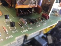 This leads me to believe that the original SCR might not be a E0102. The front is blown, so I thought it was an E0102 by reading this post: https://68kmla.org/forums/index.php?/topic/20838-macintosh-128k-240v-analog-board-component-identification/?p=211733 I could solder a trimmer instead of R45, but I don't think going under 220 Ohms is a good idea | |
| Posted by: techknight on 2016-09-23 16:07:43 I think you need to go greater than >1K for the R45. Not lower. Lower would cause it to trigger sooner. | |
| Posted by: Ferrix97 on 2016-09-23 16:12:46 I'm not an EE (I study telecommunications), but I think I should increase the resistance on the gate (by adding a resistor) to limit the current and lower R45 to bypass some current around the gate cathode junction, to make it less sensitive | |
| Posted by: techknight on 2016-09-23 16:24:51 There is no gate resistor for a reason, the circuit is already setup and tuned to operate in a certain window. You can adjust the resistors that are already there and make it work fine. I would start with R45. And for the record, I am an EE. My day job. Curious what I build? Well. Ill show ya! https://www.facebook.com/majordisplay/ | |
| Posted by: Ferrix97 on 2016-09-23 16:29:05 Tomorrow (actually, later today) I'll swap the resistors with trimmers (I usually put 2x the original value to have some room both ways) and see what happens. Also, where is R60? I cannot find it on my schematic (probably because I'm way too tired) | |
| Posted by: techknight on 2016-09-23 17:03:34 I was looking in one of larry pinas book, describes the operation of Q10, etc... Personally I dont like the design of this switcher supply. Probably since it was the early days of SMPS supplies, it used a crazy method to make it work. However, I refuse to believe that SMPS PWM controller ICs didnt exist in these days, so maybe it screams cheapness as well.. | |
| Posted by: Ferrix97 on 2016-09-23 17:10:01 The Apple II was one of the first computers to use a SMPS, and the Classic also uses an IC that was probably around when the Mac was first made, but I guess they thought "why bother improving a thing that already works?" | |
| Posted by: Ferrix97 on 2016-09-25 07:12:07 So far I've gone from bad to worse: by decreasing R45 to 200Ohms and increasing R44 and R48 to 1K, I've only gained about 7 volts or so, but now the screen is wobbling (or should I say twerking?) | |
| Posted by: Ferrix97 on 2016-09-25 08:17:53 Here are a few measurements: Unfortunately my digital scope is not isolated and the Idea I had in mind (hooking it up to a UPS) only lasted for a few minutes. So I had to use an old 15Mhz Philips with a million hours on the CRT This what I get on the Gate of Q10 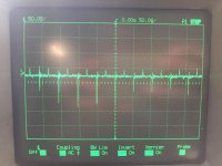 This is test point 6 (according to Apple's schematic), or the emitter of Q9 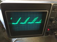 This is test point 5, or the base of Q11 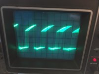 | |
| Posted by: techknight on 2016-09-25 15:33:25 ok, then try going the opposite way... You will have to experiment here because it appears the circuit is very sensitive to the exact type of SCR you use. | |
| Posted by: Ferrix97 on 2016-09-25 15:39:33 I think increasing R45 is going to make the circuit even less stable. I also tried changing R44 and R48 (which should make a voltage divider) to no avail. No matter what I do, it becomes less stable or the display starts wobbling | |
| Posted by: techknight on 2016-09-26 14:15:09 Then absolutely none of this is making any sense. if it works with the original, but not replacements then somethings wrong somewhere... Also, to re-iterate the pins 1 and 3 on modern triacs are swapped compared to the original E0102. Thats all I can say. | |
| < 3 |