68kMLA Classic Interface
This is a version of the 68kMLA forums for viewing on your favorite old mac. Visitors on modern platforms may prefer the main site.
| Click here to select a new forum. | |
| Backlit Portable with broken display cable | |
| Posted by: Ferrix97 on 2015-06-11 05:02:20 Great, thanks! the connections between the flat cable connector and CN1 do match, the numbering is the same, because CN1 is designed for another type of cable (flat ribbon), it has the even numbered pins on one side and the odd numbered pins on the other. the first and last two numbers are written on the silkscreen of the PCB If i remember correctly, there were two o three pins that didn't go anywhere, on both connector. there wasn't continuity between the two pins on the two connectors | |
| Posted by: snuci on 2015-06-11 17:44:53 Okay, here's some pics. If you need a more detailed pic, let me know and good luck! 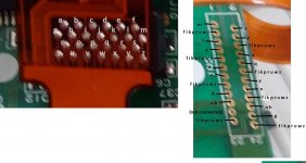 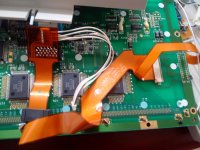 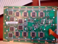 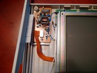 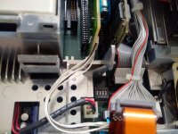 This is what you'll get when you fix it so don't give up! 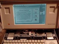 | |
| Posted by: Ferrix97 on 2015-06-12 03:38:48 Thanks to snuci I was able to fix the display cable! But I am still stuck on the same problem described in my previous posts I made a video showing the issue, it's here. (it's starting to look like the Giant from Halt And Catch Fire) | |
| Posted by: snuci on 2015-06-12 03:49:52 Just saw the video. I'm not sure you're waiting long enough for it to actually start up. I haven't done any timing but it seem to take a good 30 seconds for things to come to life and I'm not sure if you hooked up the backlight but it doesn't come on when the screen goes black on start up. It doesn't turn on until almost partial boot up. I would say it take 5 or 10 seconds just to hear the hard drive come on. Are you hearing this, at all? It does look like normal start up until you remove power. When you get the start up beep, wait at least 30 seconds. Mine looks dead until it springs to life and the backlight is not on until then. There's also a creaking sound, what is that? Edit: for clarity, I mean "comes to life" AFTER the screen goes black and clears. It's an old computer and it needs a little extra time to get moving 🙂 | |
| Posted by: Ferrix97 on 2015-06-12 04:06:57 the creaking sound was produced only after the sad mac. i don't know why. currently the backlight is non connected, I haven't made the cable yet (a I guess I'll need you help for that) right now I have no drives connected to it. after the screen clears, the current drops from 0.6A to 0.1A, which seems a bit low. I left it there for a couple of minutes, nothing... EDIT: after waiting, unplugging, rebooting... it finally decided to stay on the back screen after the chime. after a while the display started fading, so i hit the reset button and the display turned black again, current was hovering at about 0.8A. at this point I heard a loud POP! coming from my instrument rack, maybe one of the capacitors inside my bench power supply decided to blow. I was recording a video when that happened. I may upload it later... EDIT 2: whatever blew it was not involved in the portable setup, my power supply is fine (the filter cap is a bit dry, tho) and the portable seems to show the same problem, but now the black screen does not go away immeditely | |
| Posted by: snuci on 2015-06-12 04:36:36 I am going on the assumption that you would have previously fried something if there was a short in your Portable motherboard/display. Hopefully your bench power supply POP was a coincidence. I am taking a guess at this but I could see the difference in amperage when the screen goes out because it's drawing no current and the the spike to 0.6A you are seeing is the display firing up and then going dim. I'm not sure if 0.1A is normal for just the motherboard. Someone else will have to chime in here. Now that you have the cable properly doe, is there any difference if you disconnect it? If it's soldered, it will be hard to do but just checking. | |
| Posted by: Ferrix97 on 2015-06-12 05:25:48 There is no difference in powering the system with or without the cable. when the system is completely off, it draws almost next to nothing (like 0.02A), when i push both the reset and NMI buttons, it goes to 0.4A, when is showing something on the display is between 0.4 and 0.7A EDIT: here is the video | |
| Posted by: snuci on 2015-06-12 06:00:13 I can try to take a video at some point for reference. I don't have anything that can measure amperage, unfortunately, or that would have been useful as well. I have an ancient camcorder. Hopefully it can record straight to computer but I doubt it. | |
| Posted by: Ferrix97 on 2015-06-12 07:09:46 if you need to measure a limited amount of current, you can put a resistor in series with the load and measure the voltage across it, you can then get the current flowing thru the load by using the Ohm's law. | |
| Posted by: techknight on 2015-06-14 06:25:17 The hybrids go bad these units and will exert the same symptoms you see. this is AFTER a recap BTW. A quick fix is to put a 1 Meg ohm resistor between pins 18 and 16. Also, there are pull-up resistors ,and 1 UF capacitors that attach to both the NMI and Reset buttons, if they go bad, or if there are broken traces there, the same thing will happen. | |
| Posted by: Ferrix97 on 2015-06-14 06:28:38 Thanks, once I get some free time I'll check the hybrid and the two caps. Yes, the unit has been completely recapped | |
| Posted by: snuci on 2015-06-14 07:48:14 FYI, I uploaded a quick video (using my phone) so the audio isn't great but hopefully, you can hear when it starts up. https://youtu.be/Rd1oRmYyWbI | |
| Posted by: Ferrix97 on 2015-06-14 08:31:00 I soldered a 1 Meg resistor on pin 16 and 18 (on the bottom of the PCB), but it still shows the same problem | |
| Posted by: techknight on 2015-06-14 14:19:41 no no no. Pin 16 and pin 18 of the LTC1040 itself. not the hybrid pins. You would have to solder direct to the pins, and fold the resistor over where it sits on top of the LTC1040 if its done correctly. | |
| Posted by: Ferrix97 on 2015-06-15 01:18:05 I moved the resistor to the two pins of the LTC1040, but the system still shows the same problem! the system does that only when powered from the right side of the connector. if I plug only the left one, or both of them, it shows no signs of life. | |
| Posted by: techknight on 2015-06-15 04:53:40 Well time to break out the O-Scope and see whats going on with the LTC1040CN. Also, please verify that the RESET/NMI buttons are connected to the pull-ups, and that the pull ups are connected to VCC. And make sure the caps are connected to them as well, And make sure the two buttons also ring back to the MISC GLU. | |
| Posted by: Ferrix97 on 2015-06-15 05:23:02 Do you have a schematic for it? just to locate the two GLU pins. also, which pins (on the LTC1040CN) should I probe? EDIT: the switches are indeed connected to the two pull-up resistors (on the bottom of the PCB), those resistor are connected to VCC (+5V?, I checked continuity using the VCC pin on a 74-series logic chip present on the board). The caps are connected to the switches (for debouncing?), if I got the numbering right, reset goes to the last pin of the GLU, while NMI is on pin 26. | |
| Posted by: uniserver on 2015-06-15 06:02:28 there is no schematic for the portable, feel free to make some though and share em!! | |
| Posted by: Sherry Haibara on 2015-08-08 03:52:58 Ok guys, I've got a great news to share with you: my portable now boots! 🙂 Well, sort of. It's still got problems, but we've managed to get something out of it. Ferrix has managed to get his hands on another portable that exhibits a problem quite similar to mine, so he thought he could probably get somewhere by comparing and swapping components between the two. Here are his results: 1) The portable fires up smoothly and pretty much consistently if it's overvoltaged: apparently putting 7.46V directly on the battery connector manages to keep it alive and happy, but if the voltage is lower it doesn't work. 2) The portable dislikes any additional load on the rails: in order to have a boot, he needed to disconnect both the hard drive and the internal floppy drive; even if just the floppy drive is connected, each attempt to access it results in an almost instant reboot. Number 1+2 suggests to me there must be something wrong somewhere in the voltage regulation area / power supply circuitry. 3) If both hard drive and floppy drive are disconnected, the system boots but the display shows something like this. Here's the cursor:  Here's the blinking floppy:   Here's the video of it booting from a zip drive: http://v8.tinypic.com/player.swf?file=nfmd5l&s=8 4) If the display is also swapped with the one coming from the other portable, we get a nice and solid picture:   All this makes me think that: 1) The logic board itself must be working ok: probably no rotten traces or anything, at least not concerning any "major" part of the system. 2) Something must be wrong with the power circuitry, since it needs an overvoltage to get going. 3) Either the video cable still has something wrong, or the display itself is fried. So, what do you think? Where should we go from here? Thanks! | |
| Posted by: techknight on 2015-08-08 08:27:12 Meter the 5V rail feeding the system, while adjusting your input voltage. A variable DC Bench supply would be preferable here. that 5V rail should be a rock solid 5.2VDC even down to 6.3V input voltage. If it is not, then something is wrong with the Hybrid, or the MOSFET itself is bad. it is a P-Channel mosfet. the LTC1040 forms a window comparator, that when the input voltage drops below 5.9V, it will lock out the 5V regulator so it falls to 0v. The other side of the comparator is used to tell the system whether the battery is in a charge state, or a discharge state. the window comparator senses the AC adapter voltage versus the battery voltage via a sense resistor, and will latch on the next oscillator pulse (internal to the LTC1040CN), and switch on the charging circuit. or not. There is a small 8pin op-amp in the top left corner of the hybrid, its responsible for regulating the 5V rail. its error output feeds the MOSFET itself. if the MOSFET is bad, and the R(ds) is too high, it wont bring the voltage up high enough. Likewise if there is something bad on the hybrid, the same thing happens. From my experience, the hybrids that exhibits the most problems are the ones that look "discolored" from tons of cap goo getting into the ceramic substrate. The most common thing is, the Goo changes the cross-conduction between traces, and creates parasitic resistors that screw things up. This cannot be fixed for the most part, However, the closest thing to the caps is the resistor/capacitor network that forms the latching oscillator for the LTC1040. When the oscillator does not run, it will cause the portable to have random no-power at all symptoms, or no-charging indicator. Anywhere from 1Meg to 100K I have been able to get the oscillator started again. But if the damage is extensive, it may have affected other circuits as well. The only fix is to reverse-engineer the Hybrid and create a new PCB with equivalent parts. | |
| < 3 > |