68kMLA Classic Interface
This is a version of the 68kMLA forums for viewing on your favorite old mac. Visitors on modern platforms may prefer the main site.
| Click here to select a new forum. | |
| SE/30 & Micron Xceed & clear plastic goodie | |
| Posted by: Bolle on 2017-09-03 09:37:16 Sweet, thanks guys. The information and pictures are much appreciated. I think I am having enough input now to whip something together. The board is nearly finishe. Now I have to get my CNC mill up and running again before I can get the board onto copper. This might take some time. I will report back on how things work out or if any questions arise. | |
| Posted by: Bolle on 2017-09-10 12:08:44 Small update: My neckboard is going to look like this: 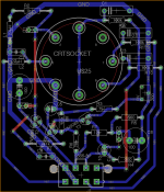 When using the TO92 package for the transistor things get a little bit tight if I keep traces thick enough for my milling machine to mill them out properly. I had to trick around a little bit by faking a layer 1 trace on T1 and will just bend one of its legs to fit into the hole further away so I can route a trace below it and do not have to add another jumper wire. If things work out I can share the Eagle files as well. | |
| Posted by: Bolle on 2017-09-25 12:09:35 Here we go: 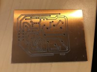 Not perfect but should work for a first test. Now on to getting everything soldered down and getting the harness together. | |
| Posted by: Bolle on 2017-10-01 10:06:11 Finally I had the time to finish everything up. My SE/30 is up and running with internal grayscale :simasimac:  Here is what my selfmade neckboard looks like after assembly: 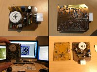 I managed to get this done as single layer with only one wire jumper on top. Size is roughly the same as the original CRT board. I wanted to keep size as small as possible to make it fit in together with the backpanel board of my Asante MacCon. Making the harness was easy with the wiring diagram found in the patent files from Micron (and thanks to joethezombie for pointing out the missing pin count on said diagram). It came out like this: 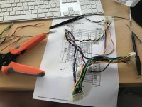 And here is everything stacked up and tucked together... things get tight in there with two cards stacked on top of each other and the wiring harness: 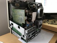 Now the only thing missing for the ultimate grayscale SE/30 is a socketed Powercache }🙂 | |
| Posted by: Trash80toHP_Mini on 2017-10-01 10:35:55 It's a BEAUTIFUL thing! [😉] ]'> | |
| Posted by: BadGoldEagle on 2017-10-01 11:04:26 Nice work! | |
| Posted by: joethezombie on 2017-10-01 11:10:02 Yeah! Absolutely magnificent! Nearing the epoch of SE/30 goodness! Have you tried the Micron Virtual Video on it? It surprises me everytime I enable it just how silky smooth it works. | |
| Posted by: 68krazy on 2017-10-01 16:12:44 You’re approaching SE/30 nirvana there. Great work! | |
| Posted by: sambapati87 on 2017-10-02 09:22:04 That's a beautiful thing | |
| Posted by: EkriirkE on 2017-10-26 23:31:48 Now that looks slick. | |
| Posted by: kreats on 2017-10-27 04:34:27 any chance you could make this available as a shared project on osh park? | |
| Posted by: just.in.time on 2017-10-27 20:44:38 That is amazing!!! Good job 🙂 | |
Posted by: Bolle on 2017-10-31 14:37:31any chance you could make this available as a shared project on osh park?Is there an easy way to do that without having to sign up with them? Only way to upload something gets me to their PCB order thing unless I am not seeing some hidden Share-your-Design-here-button. Cooked up a V2 already that does not need any wire jumpers and is completely single layer so everyone can make those easily at home: 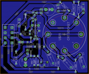 I can send the files to everyone who wants them. | |
| Posted by: apm on 2017-10-31 14:56:40 Nice work! I'd be interested in the design files for my resolution hack project (PM me?). I'm curious about the voltage level of the video signal when it arrives from the Micron to this board. Is it more similar to VGA (0.7V) or to the TTL video (5V)? Are you able to measure it with a scope? Thinking ahead to what will be needed to adapt other video sources. | |
| Posted by: Bolle on 2017-11-01 02:34:24 The Micron documents say that the card outputs 0-1V which then is amplified on the neck board to 0-30V. So this could probably used to get a VGA signal to show at least something on the screen. | |
| Posted by: kreats on 2017-11-01 08:18:07 You'll have to sign up with them yeah - could just use dummy info I suppose. It really is the best way of getting the design out there though - you can order pcb's shipped worldwide for a couple of bucks - which is way easier and cheaper than making them at home. From what I gather, it has to be submitted as either:
I've never uploaded a design before - but I've ordered a few PCBs of interesting products from people who have made their designs available (mainly for game consoles) with good results. | |
Posted by: Bolle on 2020-01-04 12:27:38View attachment 14394When ordering PCBs anyways I thought it might be time to polish this up a bit... From homemade in a kind of period correct style to new and shiny: View attachment 30928 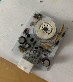 Looks beautiful, I guess I will need one of those clear cases someday... 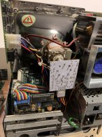 | |
| Posted by: olePigeon on 2020-01-05 11:34:48 Ooooo. I always like the white PCBs. That'd look great in the clear case. | |
| Posted by: snuci on 2020-01-06 09:38:02 I somehow missed this thread. @Bolle can you send me the file or is it available as a shared project? | |
| Posted by: Bolle on 2020-01-06 11:59:50 Sure, here you go. -> View attachment Micron_neck_clone.zip The values and everything match the schematic that's flying around the net from the old Gamba days: 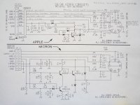 Most parts can be sourced from a donor Apple neck board. Edit - and in case you need the gerbers: View attachment crtneck_gerbers.zip | |
| < 2 > |