68kMLA Classic Interface
This is a version of the 68kMLA forums for viewing on your favorite old mac. Visitors on modern platforms may prefer the main site.
| Click here to select a new forum. | |
| LCD Replacement for the Macintosh Portable | |
| Posted by: campbellashe on 2026-06-09 14:53:31 I’m looking forward to your solution. Great that you took this on. Just wondering if you two were collaborating. | |
Posted by: Froggy814 on 2026-06-09 18:08:22I’m looking forward to your solution. Great that you took this on. Just wondering if you two were collaborating.Thanks! That would have been awesome to collaborate with him. He seems to have a lot of knowledge about the portable compared to me, but unfortunately I don't have a good way to contact him. On a side note, do you have a good idea on what type of cable I should use to take the odd connector apple used to make it something else becuase the 2.54 spacing header and cable will just not fit inside the portable's LCD bezel, it's too tall. I was thinking maybe I should use a regular very small/thin flat flex cable like the ones you can find on basically every electronic that connect boards together. Do you have any ideas on that? | |
| Posted by: campbellashe on 2026-06-09 18:28:32 Yes. The flat flex cable is a good idea with a small zif style connector. | |
Posted by: Froggy814 on 2026-06-09 19:49:52Yes. The flat flex cable is a good idea with a small zif style connector.Great! It'll make the adapter PCB and the controller PCB much smaller too! I just wanted to know if it was a good idea. | |
Posted by: Froggy814 on 2026-06-10 16:03:41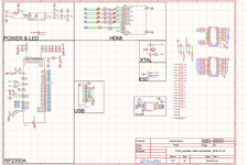 Alright, the schematic is coming together. I've changed it so many times now! | |
| Posted by: Froggy814 on 2026-06-10 16:05:47 Does anyone have a 3d scanner and has the ability to scan the bezel for the lcd on the portable? Because otherwise the screen is going to be tiny! I am also asking for power consumption reasons. | |
Posted by: Froggy814 on 2026-06-12 10:57:08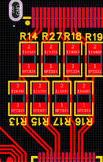 Do these HDMI traces look like they are run good? I think they will be okay. The Maximum length difference between traces is 66mils and it should have 100ohm of differential impedance. | |
| Posted by: Froggy814 on 2026-06-12 17:36:56 Review Time!!!! 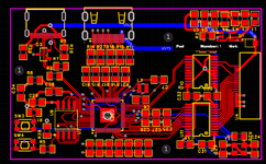 Top of PCB, none of the inner layers exposed which are: power and gnd. 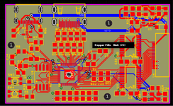 Inner layers exposed. 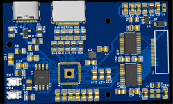 Top in 3D 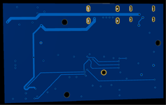 Bottom in 3D Any questions? Things I should fix? Thanks! | |
| Posted by: zigzagjoe on 2026-06-12 20:39:32 Off the cuff, some quick thoughts.... Decoupling capacitors must be as close to the RP2350 as possible and wired one per power pin on the chip. That advice goes for all other power pins on other parts too. Oscillator must be as close as possible to the chip and take caution with the grounding of the caps. Use an array of vias instead of one large plated hole under the RP2350. Trace clearance looks somewhat tight, suggest increasing it and using smaller passives to give you more flexibility. I didn't really look at the rest of the design - switching regulator in the corner looks a little odd, especially inductor - or validate the schematic. My advice: consider using a pico module for v1 as that will eliminate much of the sensitive critical design work. But if you want to do the laid-down RP2350, I would recommend looking at some tested open source designs and borrowing as much as possible of the layout. Also read the design guide provided by Raspberry PI and take it as gospel, they provide a lot of excellent advice in there. | |
Posted by: Froggy814 on 2026-06-13 07:35:21Off the cuff, some quick thoughts....Thank you very much for the advice! It's hard to find sound advice, so I just followed the schematic for the Waveshare. Thank you soooooooo much! | |
| Posted by: Joopmac on 2026-06-13 10:45:02 Following this. Have a lot of portables, always frightened of tunnel vision | |
Posted by: Froggy814 on 2026-06-13 13:00:34always frightened of tunnel visionSame here! | |
Posted by: Froggy814 on 2026-06-14 17:04:05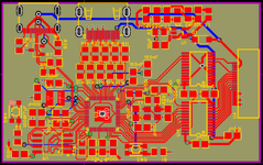 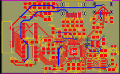 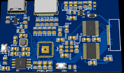 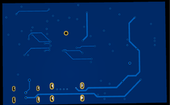 Alright, need quick feedback, my brother is ordering pcb's tomorrow and i don't want to pay for shipping (I know but it's expensive). What is wrong and needs fixing? Thanks! | |
| Posted by: David Cook on 2026-06-14 19:44:17 1. Add a pair of holes so that a loop of wire can be soldered in place for a ground test point. It will make oscilloscope/multimeter testing much easier. 2. If you have spare wires in the cable, bring those out to a header (along with +5 and ground) so that we can hack a brightness control via software. Is this for both the M5120 and M5126? Do you still plan on a ribbon cable connector because it looks like you've switched to a flat flex. | |
Posted by: Froggy814 on 2026-06-14 19:50:44Is this for both the M5120 and M5126? Do you still plan on a ribbon cable connector because it looks like you've switched to a flat flex.Not quite sure what you mean by that? | |
Posted by: Froggy814 on 2026-06-14 19:53:082. If you have spare wires in the cable, bring those out to a header (along with +5 and ground) so that we can hack a brightness control via softwareI don't have any spare wires in the cable, but i can make a pin header with gpio coming out for brightness modifying. I will do that thank you! | |
Posted by: joevt on 2026-06-14 20:04:36Not quite sure what you mean by that?M5120 and M5126 are two models of Macintosh portable where the latter is backlit and the former is not. Ribbon cable and flat flex are two different types of cabling. What kind of cabling are you going to use? What is U4 going to be? It looks like you made the decision to switch to flat flex at https://68kmla.org/bb/threads/lcd-replacement-for-the-macintosh-portable.52408/post-592677 | |
Posted by: Froggy814 on 2026-06-14 20:10:20Ribbon cable and flat flexBoth! I am making an adapter hat that will go to the ribbon with a plug on the end for flat flex that you can buy readily at amazon. | |
Posted by: Froggy814 on 2026-06-14 20:10:51M5120 and M5126 are two models of Macintosh portable where the latter is backlit and the former is not.If the pinout is the same then yes. | |
| Posted by: liamur on 2026-06-15 10:39:32 What inductor did you use on the RP2350's internal regulator? The RP2350 is very sensitive to what inductor is on the board and how it's arranged relative to the chip, to the point that Pi Foundation had a specific model of inductor custom manufactured with polarity markings so that people can make boards that run at max efficiency. If you haven't verified your design against the official recommendations, you should. Also, make sure you have a pull-up on the RUN pin so that the chip isn't in reset all the time. This isn't really mentioned in that document and it matters (I learned the hard way). I can see that you aren't using the recommended inductor layout. That may not be an issue but you should be aware of the potential for a non-functioning board. If you've already ordered the boards, disregard this 🙂. | |
| < 2 > |