68kMLA Classic Interface
This is a version of the 68kMLA forums for viewing on your favorite old mac. Visitors on modern platforms may prefer the main site.
| Click here to select a new forum. | |||||||||||||||||||||||||||||||
| Schrockwell's S3/30 Reloaded build | |||||||||||||||||||||||||||||||
| Posted by: SinclairSoftware on 2025-10-28 12:37:00 Watching this project slowly come together is very inspiring! | |||||||||||||||||||||||||||||||
| Posted by: CptnCodon on 2025-10-28 16:00:19 Wow! That’s very inspiring. Great work, and thanks for sharing. | |||||||||||||||||||||||||||||||
| Posted by: schrockwell on 2025-10-29 11:13:16 Well, that was short-lived. A little later I plugged in a keyboard and mouse, and now it won't boot. The failure was gradual. The screen and audio started wigging out, and now the display won't come on at all, and certainly no startup chime. There was some high-pitched squealing that might have been coming from the flyback transformer. I suspect the power supply needs a recap, which I will tackle next. I just hope it didn't take damage anything else. | |||||||||||||||||||||||||||||||
| Posted by: schrockwell on 2025-10-29 18:25:25 I recapped the CR-44 power supply with the kit from Console5. All went well. Thank god for the Hakko; I got it done in just 90 minutes. Here are the output voltages, unloaded. No major changes.
After reassembly, the problem persists. I managed to capture a short video: View attachment IMG_0415.MOV Sometimes it plays a complete chime and shows the cursor, but then freezes. Other times it just shows garbage on the display, or the display is blank. Definitely feels like an intermittent failure of an analog component. I also got an error code once: 0000000F 00002802.I checked the voltages on the floppy connector:
Note that there is NO voltage on pin 5, where -12V is expected. Could that be the culprit? Maybe a bad voltage regulator in the PSU? | |||||||||||||||||||||||||||||||
| Posted by: schrockwell on 2025-10-29 21:31:48 I measured the -12V line at -11.7V at the power supply connector in-circuit. So the power supply is working, but the bad reading at the floppy connector still might be a clue. | |||||||||||||||||||||||||||||||
| Posted by: schrockwell on 2025-10-30 08:08:35 Actually, pin 5 on the floppy connector is N/C, so that was a red herring. 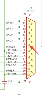 Currently, there is startup chime or display at all. I did find and repair a couple cold solder joints on the analog board, but no improvement there. I'm pretty stuck at this point. | |||||||||||||||||||||||||||||||
| Posted by: dochilli on 2025-10-31 02:30:07 If I remember it right, there is no -12V at SE/30 computers at the floppy port. | |||||||||||||||||||||||||||||||
| Posted by: schrockwell on 2025-10-31 06:57:55 Yup, that is what I found as well. I realized that I did not recap the analog board yet, so that is the next step. | |||||||||||||||||||||||||||||||
Posted by: SinclairSoftware on 2025-10-31 07:34:41Yup, that is what I found as well.The analog board was pretty easy peasy from what I recall from working on mine. Even used hot glue on the caps so they wouldnt move around and break solder joints. Felt super professional and fancy afteword lol. | |||||||||||||||||||||||||||||||
| Posted by: frontein1 on 2025-10-31 23:15:37 @schrockwell if you get to the point of selling any completed board builds, I think you'll have some buyers! I'd like to get in line 🙂 | |||||||||||||||||||||||||||||||
Posted by: schrockwell on 2025-11-01 10:13:16@schrockwell if you get to the point of selling any completed board builds, I think you'll have some buyers! I'd like to get in line 🙂That would be quite the undertaking. It would be really difficult to price them low enough to make it worth the cost of parts and time. I think it would have to be a labor of love for someone with ample free time. | |||||||||||||||||||||||||||||||
Posted by: croissantking on 2025-11-01 10:59:11I recapped the CR-44 power supply with the kit from Console5. All went well. Thank god for the Hakko; I got it done in just 90 minutes. I’ve had an issue like this. Couple of things to check - solder work around the GLUE chip (possible poor connection), and sagging 5V line (possibly causing a twitching reset line). When you come to recap the analog board, check all the sockets for dry joints on their pins. Great work so far - you’re very close to solving it. | |||||||||||||||||||||||||||||||
Posted by: schrockwell on 2025-11-03 13:27:21I’ve had an issue like this. Couple of things to check - solder work around the GLUE chip (possible poor connection), and sagging 5V line (possibly causing a twitching reset line).Thanks, I checked both of these things. I even asked my wife, who has experience with electronics QA, to look it over. No improvement, unfortunately. And the analog board recap went smoothly but did not change anything. I dusted off the scope and began poking around, starting with the oscillator output. The frequency is good, but I was surprised to find a jaggy triangle waveform with a DC offset. I was expecting a sine wave or square wave centered at 0V. Does this look normal? 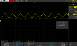 I also probed the reset line at the switch, and after power-on it goes high and is never pulled low. | |||||||||||||||||||||||||||||||
| Posted by: schrockwell on 2025-11-03 15:21:26 It sure seems like 1.120V is not low enough to trigger a logic low, since the specified threshold is 0.8V. 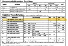 | |||||||||||||||||||||||||||||||
| Posted by: schrockwell on 2025-11-04 08:49:37 Here's the C32M line, measured from the output of UH7 at R28. It's pretty sad-looking. 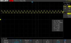 | |||||||||||||||||||||||||||||||
| Posted by: schrockwell on 2025-11-04 13:44:14 I desoldered Y2 from the board and tested it directly with a 5V bench supply. The results are very similar to the in-circuit plot from before. The leads were too short to stick in a breadboard, so I couldn't set up a proper test circuit. But connecting 5V, ground, and the output directly should be good enough, right? Anyway, I think this oscillator is cooked. I may have overheated it when removing it from the donor board. Will have to source a new one. 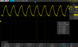  | |||||||||||||||||||||||||||||||
| Posted by: codevonlux on 2025-11-04 13:48:46 I think I have a few spares of the oscillator (new), DM me if you need any. | |||||||||||||||||||||||||||||||
| Posted by: schrockwell on 2025-11-12 10:45:14 New oscillators came, no change or improvement. The C32M line at pin 1 of UI7 still looks very wrong - it's the correct frequency, but a triangle wave from 3.2-4.3V which is definitely not TTL levels. So I still suspect something is still wrong with the clock generation, perhaps UH7? I also noticed after being powered on for a few minutes, the 68030 becomes very warm, bordering on hot. | |||||||||||||||||||||||||||||||
Posted by: croissantking on 2025-11-12 11:26:56New oscillators came, no change or improvement. The C32M line at pin 1 of UI7 still looks very wrong - it's the correct frequency, but a triangle wave from 3.2-4.3V which is definitely not TTL levels. So I still suspect something is still wrong with the clock generation, perhaps UH7? Check the connections to UH7 carefully. The footprint on the Reloaded board makes it difficult to solder as the pads are almost completely hidden by the chip, so poor connections are common. Check to make sure that adjacent pins aren’t bridged, too. I also noticed after being powered on for a few minutes, the 68030 becomes very warm, bordering on hot. That doesn’t seem right, the 030 chip hardly gets warm on my boards. | |||||||||||||||||||||||||||||||
Posted by: schrockwell on 2025-11-12 12:08:49Check the connections to UH7 carefully. The footprint on the Reloaded board makes it difficult to solder as the pads are almost completely hidden by the chip, so poor connections are common. Check to make sure that adjacent pins aren’t bridged, too. Thanks, I have done a lot of fiddling with UH7. It's socketed, because those pads were just too impossible to solder directly, like you said. I tried reflowing the socket pads, cleaning and re-tinning the pins on the PLCC... no luck. That doesn’t seem right, the 030 chip hardly gets warm on my boards. I am hoping the heat is just a side-effect of the CPU being stuck in some reset state because there is no clock. Unsocketing both the CPU and UI7 has no effect on C32M, so I don't suspect those parts are damaged. I also checked C16M at pin 2 of UI7 and it's just DC, no clock at all. Which I think makes sense, because as far as I can tell, UI7 generates C16M, I assume as a frequency divider from 32 MHz input down to 16 MHz output? I'm totally shooting in the dark here. If anyone can probe the output of Y2, or C16M, or C32M, I would love to see what the correct signals look like. 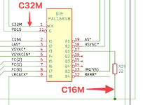  | |||||||||||||||||||||||||||||||
| < 2 > | |||||||||||||||||||||||||||||||