68kMLA Classic Interface
This is a version of the 68kMLA forums for viewing on your favorite old mac. Visitors on modern platforms may prefer the main site.
| Click here to select a new forum. | |
| TashSync: Macintosh Video Sync Signal Converter/Generator | |
Posted by: Tashtari on 2025-07-02 01:55:54is there any way of tuning INTOSC on the PIC12? (Doesn't look like those have OSCTUNE).Oh, interesting, the 12F1501 doesn't have OSCTUNE (for that matter, neither does the 10F320/322)... that's strange, I never noticed that before. OSCTUNE would be the usual way to fine-tune the oscillator, if it existed, and I don't see anything that replaces its functionality. I did try something related to what you're suggesting using the NCO, which should in theory be able to match a frequency with finer detail than the oscillator can provide (albeit rounding pulses to the nearest 16 MHz clock tick), but wasn't able to match the target frequency with sufficient precision before the code involved got too long and time-consuming, so I abandoned the approach. Might just have been a skill issue on my part, though. (just spitballing an interesting problem, I hope I'm not suggesting ideas you've already discarded)No worries at all! I love this stuff. | |
| Posted by: Tashtari on 2025-07-02 15:03:28 As I continue to chip away at this, I'm getting more into the mindset that a single adapter to do All The Things is not the approach I want to take... I think I'd rather make different pieces of firmware for the PIC10F320 that handle specific cases and adapters to go with them. One adapter for the IIsi/IIci, one for the Toby, &c. That way, instead of having one adapter that you move around, you associate multiple adapters 1:1 with computers, more or less permanently, and plug a modern monitor into it like normal. Plus, I like how small and cute I can make an adapter when 90% of the board real estate is taken up by the connectors and the PIC and friends are able to fit into the remaining corner. I now have three JLCPCB orders pending with boards pertaining to this project (mostly, anyway, I have a few other tricks in the pipeline). Still need to make an IIgs board, though, as it has slightly different needs than the Mac boards do (damned thing provides -5V and +12V but not +5V, whose brilliant idea was that?), but I have a Mac board in the order - I'm trying the bunch-of-diodes approach, hopefully it works. I'm excited. I have projects that plug into just about every port on the back of a Mac, but up until now I did not have one for the video port... | |
Posted by: rfc6919 on 2025-07-02 23:19:36Oh, interesting, the 12F1501 doesn't have OSCTUNE (for that matter, neither does the 10F320/322)... that's strange, I never noticed that before. OSCTUNE would be the usual way to fine-tune the oscillator, if it existed, and I don't see anything that replaces its functionality. I did try something related to what you're suggesting using the NCO, which should in theory be able to match a frequency with finer detail than the oscillator can provide (albeit rounding pulses to the nearest 16 MHz clock tick), but wasn't able to match the target frequency with sufficient precision before the code involved got too long and time-consuming, so I abandoned the approach. Might just have been a skill issue on my part, though. I think that would give you tearing still - even the 16MHz clock boundaries will be a touch under 2 pixels wide, drifting in and out of sync with the pixel clock. The way I'm thinking would need fine frequency control over that clock to line it up with the inbound hsync pulses (using an JK latch in one of the CLCs as a PLL phase detector or something, those look like cool little blocks) But without a real oscillator tuner my mind is going to "solutions" like dumping current through the remaining output pin to warm up the mcu and push the RC oscillator frequency up. A fun idea, but real art-project stuff and not viable in your power budget 🙂 | |
| Posted by: rfc6919 on 2025-07-03 00:08:44 Overall I think my idea is the wrong approach. It's probably not possible with this part to line MCU clock edges up with pixel clock edges, so a fully synthesised hsync will inevitably give tearing during image scan. Passing the actual hsync from wherever through will mean at least the displayed image doesn't tear, and if things aren't so accurate during vsync then it probably(?) doesn't matter. | |
Posted by: Tashtari on 2025-07-03 03:07:51I think that would give you tearing stillYeah, most likely. I was mainly intending to use it over the flat interval in the Toby card's composite signal where the signal has to be synthesized, rather than full time. Passing the actual hsync from wherever through will mean at least the displayed image doesn't tear, and if things aren't so accurate during vsync then it probably(?) doesn't matter.This is what I'm depending on. =D So far it seems to hold true, fingers crossed that that continues to do so, because the 10F320 only has one CLC which I use to output the horizontal sync signal, and the vertical sync signal is under firmware control, which means it's necessarily less accurate. Definitely a lot of testing to do. | |
Posted by: Tashtari on 2025-07-04 05:25:20So far it seems to hold true, fingers crossed that that continues to do soSo far so good! I have PIC10F320 firmware now that I've confirmed to work on the IIsi on at least one monitor which I know doesn't support sync-on-green. Same should work on the IIci, though I don't have one of these to test on. PCBs on the way, and we'll see whether I'm physically capable of soldering SOT-23 chips. Meantime, on to the Toby... | |
| Posted by: Tashtari on 2025-07-05 10:02:38 The Toby firmware is working! ...From a simulated signal, at least. Don't have a real Toby card to test with (or a Mac II, for that matter). It should also work for that SE/30 card whose name escapes me that has a flat horizontal sync pulse but no serrated pulses, but I haven't set up a test signal generator for this yet. Gotta think what to do next. I like the purpose-built PIC10F320-based adapters mainly because they are so tiny and simple, but there is some appeal, too, in a more general sync processor that could be thrown at a variety of situations. I tried to do this in the PIC12F1501 but ran up against the limits of its program memory as well as of its pin configuration. I might give this another try with the PIC16F1704, which has twice the program memory as the 1501, peripheral pin selection, AND, particularly appealingly, a capture/compare peripheral - good for measuring signal periods without interrupt-and-long-loop-related shenanigans. ...But it has 14 pins instead of 8, boo. | |
| Posted by: Tashtari on 2025-07-09 08:42:23 Lot of shifting goalposts in this project. Partially the fault of my own particularities, but as usual I'm also learning more minute details of my favorite PICs as I go. With the three PIC10F320 firmwares (firmwares? firmware programs? units of firmware?) complete, I'm now trying to implement the general-purpose sync processor idea on the PIC12F1840, the same PIC TashTalk uses. It has most of the features of the PIC16F1704 and also has 8 pins, which is key, but it also has trouble waking from sleep in a timely manner when running at its full-tilt speed of 32 MHz... which kind of sucks, because the faster clock of course allows for more precise timing measurements. Maybe this particular subset of the project will just require external power as the price of its flexibility. It has one of the features from the early stages of this project that I find most interesting - contained in its detailed serial output is a little mini-trace of the vertical sync area of the signal which can not only be parsed by the firmware itself but can be used to figure out why the firmware can't synthesize separate sync signals from a particular composite sync signal. Desirable for users who have exotic Macs but not scopes. Anyway, four separate waves of PCBs hopefully arriving soon. Hope to enable new testing and maybe get something testable into the hands of interested parties... | |
| Posted by: Tashtari on 2025-07-16 10:07:18 Success! With a little help (okay, a lot of help) from @zigzagjoe, TashSync is now working on the IIsi without an external power supply! He noticed that the PIC's own protection diodes could be used in lieu of external diodes to rectify the composite sync signal to provide power as long as there was enough of a bulk capacitor between the supply and ground pins, and lo and behold, it works! At around 2.8 volts, the voltage it runs off is nothing to shout about, but it's enough, and it's stable. Circuit (TI-83 Plus style): 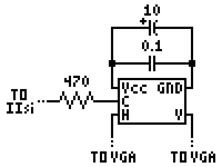 Thoughts? Is this crazy or just-crazy-enough-to-work? | |
Posted by: adespoton on 2025-07-16 14:56:01Success!That's awesome! What sort of power is hitting the outside of that capacitor? | |
Posted by: Tashtari on 2025-07-16 15:07:23What sort of power is hitting the outside of that capacitor?The 2.8 volts figure is what I measure between ground and Vcc, is that what you're asking? I'm not sure I understand the question. | |
Posted by: joevt on 2025-07-16 15:22:49Success!I'm no electronics engineer. Why are there two capacitors? Would 10 + 0.1 = 10.1 be equivelant?. One is polarized. The other is not. Why? How does the power get from C to Vcc/GND? What amount of current is being sucked from C? | |
| Posted by: Tashtari on 2025-07-16 15:50:01 These are things that I'm not going to be able to explain very well (I'm not an electronics engineer either), but I'll try - anyone who knows better, please correct me. Why are there two capacitors? Would 10 + 0.1 = 10.1 be equivelant?. One is polarized. The other is not. Why?Yes, technically a 10.1 µF capacitor would have the equivalent capacitance of both capacitors, but it's slightly more complicated than that. The 10 µF cap is electrolytic (these are, to my understanding, always polarized) and the 0.1 µF cap is ceramic (these are, to my understanding, never polarized). The electrolytic cap is bigger, the ceramic cap is faster. The idea is that the ceramic cap is able to iron out smaller fluctuations and the electrolytic cap bigger ones. Exactly how/why this works, I can't say. How does the power get from C to Vcc/GND?The GPIO pins in the PIC have internal diodes that are meant to protect the PIC, but they also allow current to flow from the pin to Vcc. Usually this isn't necessary as Vcc is conventionally powered, but here we're taking advantage of them so we can use C as a power source as well as a signal. What amount of current is being sucked from C?Somewhere in the neighborhood of 2 mA. | |
| Posted by: joevt on 2025-07-16 18:10:11 Diodes are cool. FULL BRIDGE RECTIFIER!!! | |
Posted by: CC_333 on 2025-07-16 20:02:52Diodes are cool. FULL BRIDGE RECTIFIER!!!They are! They definitely are better than Selenium rectifiers, which are finicky, bulky, and prone to releasing copious amounts of acrid, toxic smoke when they fail. Thankfully they're not a problem for virtually any computer built within the past ~45 years (we got RIFAs instead, which are decent enough when new, but they're prone to failure when they age, and when they do, they like to explode and also release lots of acrid smoke, which I'm sure isn't nontoxic. Yay?) c | |
| Posted by: Tashtari on 2025-08-08 10:39:25 PCBs are here at last! And parts... mostly. Digikey made a boob and sent me LM358s instead of PIC10F320s. But here, substituting a PIC10F322, it is!  That's a 22 µF aluminum polymer cap (used at the suggestion of @cheesestraws in lieu of a tantalum), an 0.1 µF ceramic cap, and a 330 Ω resistor installed "Japanese style", crammed into the corner with the PIC. All parts are through-hole so the board can be assembled by ham-fisted soldering iron jockeys like myself - and yet the adapter is just about as small as it can be considering the size of the DA-15 and DE-15 connectors. And it works a treat on my IIsi, natch. \o/ | |
| Posted by: finkmac on 2025-08-08 10:44:35 that's really packed in nicely. great job. | |
Posted by: Tashtari on 2025-08-09 03:19:48that's really packed in nicely. great job.Thanks. =D Smol detail to correct with the PCBs, the board is slightly too wide and the DA-15 doesn't sit quite flush with its edge - so it's going to get even smaller in the next and hopefully final revision, after which I'll offer a handful of kits for sale. I'm also spinning a passive DA-15 to DE-15 adapter with that tight little corner populated with a 6-position DIP switch so there's a solution for everyone. ...Or so I hope. My three firmware versions are for the IIsi/IIci, the Toby (and SuperMac ColorCard), and the IIgs. So far, no other cases that require active sync processing have come to my attention, but that could change. | |
| Posted by: Tashtari on 2025-08-09 03:36:09 oh, and, since I'm in a pedantic mood:  NO NO NO NO NO What we will do is set the record straight. The second letter in the name of a D-sub connector denotes the shell size, and the B in DB-25 refers specifically to the shell size that contains 25 (sometimes 44 or 52) pins. The Macintosh video connector is properly called a DA-15 and the VGA connector is properly called a DE-15. The E shell is the same size shell that contains 9 pins in two rows where it appears on the common PC serial port as DE-9 and the A shell is the same size shell that contains 26 pins in three rows where it appears on the Apple IIe LC card as DA-26. Tangentially, the 19-pin connector used for connecting external floppy drives, HD20s, and emulators thereof has no proper shell size letter as it's non-standard - it should be referred to as a 19-pin D-sub connector or a "DB"-19, with the DB in scare quotes, or maybe a D?-19... I think I'm going to start using the latter. | |
| Posted by: shirsch on 2025-08-09 07:26:44 Waiting patiently for kits to become available... Nice work! | |
| < 2 > |