68kMLA Classic Interface
This is a version of the 68kMLA forums for viewing on your favorite old mac. Visitors on modern platforms may prefer the main site.
| Click here to select a new forum. | |
| SE/30 Board Mystery Issue | |
Posted by: Phipli on 2024-04-11 13:56:35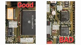 There we go, should have made this years ago 🤣 | |
| Posted by: smrieck511 on 2024-04-11 17:52:27 To my everlasting shame, I lifted the pad at C5+ ... all the other pads are OK. Would some kind person tell me where to run a bodge wire from C5+ ? or where to find a clear schematic. | |
Posted by: rickrob on 2024-04-11 19:30:18 | |
Posted by: rickrob on 2024-04-11 20:03:54To my everlasting shame, I lifted the pad at C5+ ... all the other pads are OK. Would some kind person tell me where to run a bodge wire from C5+ ? or where to find a clear schematic.C5 + connects to UB11, pin 15 and UB10 pin 15 | |
Posted by: smrieck511 on 2024-04-11 21:16:46View attachment 72457Thanks! | |
Posted by: smrieck511 on 2024-04-11 21:17:29C5 + connects to UB11, pin 15 and UB10 pin 15Thanks! | |
| Posted by: smrieck511 on 2024-04-13 05:08:57 Checked continuity for everything in the sound circuit as indicated on recap-a-mac. All that is fine. I took out the video chips and video rom and cleaned sockets with deoxit. Cleaned up as much as I could on everything else. Caps should be here by tuesday. | |
| Posted by: JC8080 on 2024-04-17 05:47:00 Here is an excellent re-drawn version of the SE/30 schematics. This was created by one of the board members here, I didn't bookmark the original post I got it from so I can't give credit where credit is due, but I'm sure someone here will know who created it. | |
Posted by: JC8080 on 2024-04-17 05:50:40You'll be fine most damage is on the surface and vias can usually be easily bypassed. The best tool you have for repair is your eyes. Spend the time inspecting every pad and via and you will see anything that looks nasty, then you can check it with a multimeter. I think we have multiple schematics for these. A reproduction board with minor changes, but will open in tools that will highlight traces for you, as well as Bomarc (not a huge fan) and possibly also Apple schematics (their early revision schematics and there is a change, but that is documented in the reproduction).Are there tools that will let you highlight traces on a Gerber file? That would be really helpful. Using the SE/30 Reloaded Gerber files with an online Gerber viewer will make following traces quite easy. I have experimented with a number of the online Gerber viewers and have found Altium (https://www.altium.com/viewer/) to be the best. It is quite responsive, some others are very slow. You can show and hide layers, making it very easy to follow a trace from point to point. | |
Posted by: smrieck511 on 2024-04-17 06:11:26Here is an excellent re-drawn version of the SE/30 schematics. This was created by one of the board members here, I didn't bookmark the original post I got it from so I can't give credit where credit is due, but I'm sure someone here will know who created it.fantastic. This is exactly what I've been looking for. Thank you. | |
Posted by: JC8080 on 2024-04-17 06:45:07fantastic. This is exactly what I've been looking for. Thank you.Definitely try out the board files with the Altium viewer too. Since it is a "map" of the board, it is very easy to visually follow a trace from point A to B. The reloaded board is not an exact copy of the original so not all components and traces are in the exact location as a stock board, but it is close enough to be helpful. The board files are on Bolle's GitHub page: https://github.com/TheRealBolle/SE30 | |
| Posted by: robin-fo on 2024-04-17 07:37:32 Huh? I thought the traces on the reloaded board were routed differently? | |
| Posted by: smrieck511 on 2024-04-17 08:41:29 well, an update… Making some progress. After a full logic board, analog board, and PSU recap, I've got sound working (it chimes). Still no video. And that problem is isolated to the logic board because this analog board and power supply work fine with other boards. The CRT is no longer making flickering snowflakes it's just dark unless I boost the brightness all the way at which point you can see the scan lines on the CRT. again, the CRT and analog board are perfectly fine. They boot other boards with no problem and the brightness is fine. so we have a video issue on what seems to be a board that's alive. Any ideas where to start. I am very unfamiliar with how to approach video problems on the logic board. UE8 looks ok and i've cleaned everything pretty well. | |
| Posted by: davewongillies on 2024-04-17 08:51:32 Pending advice from some of the more knowledgeable people around here The Dead Mac Scrolls has a few suggestions for things to look at for no video output. | |
Posted by: JC8080 on 2024-04-17 09:14:05Huh? I thought the traces on the reloaded board were routed differently?They may be, I thought they were close to the originals, but it's possible the board files would not be useful in this situation. | |
| Posted by: alectrona6400 on 2024-04-17 09:15:24 the reloaded is a 4 layer board whereas the original is 6 layer if i recall correctly... | |
| Posted by: smrieck511 on 2024-04-17 09:20:15 is it a good assumption that since it chimes, it is seeing the ROM and therefore the board is working, but there is an obvious video issue. In other words, the ROM, RAM And processor are alive? | |
| Posted by: alectrona6400 on 2024-04-17 09:22:06 yes, that usually means a successful boot... but i would check your video PAL, UE8, and the TMS4461 chips... do you get no video at all or do you just get the horizontal jail bars? | |
Posted by: JC8080 on 2024-04-17 14:28:00the reloaded is a 4 layer board whereas the original is 6 layer if i recall correctly...Got it, consider my prior suggestion fully withdrawn. 🙂 | |
| Posted by: smrieck511 on 2024-04-17 14:54:31 newbie question.. which chip is the video PAL? | |
| < 2 > |