68kMLA Classic Interface
This is a version of the 68kMLA forums for viewing on your favorite old mac. Visitors on modern platforms may prefer the main site.
| Click here to select a new forum. | |
| Color Classic video problem | |
| Posted by: ymk on 2023-03-29 17:04:10 Are you sure the pot isn't 1K? | |
| Posted by: gbcs001 on 2023-03-29 17:10:36 I measured the resistance across the terminals at 514 ohms, 514 ohms, a 0 ohms. I think that indicates a 500 ohm pot. Right? | |
| Posted by: ymk on 2023-03-29 18:51:48 Measure between the two outer terminals, not the center. The highest resistance between any two pins is the nominal value of the pot. | |
| Posted by: gbcs001 on 2023-03-29 19:30:22 Thanks. The resistance between the outer two pins measured 517 ohms. | |
Posted by: jajan547 on 2023-03-29 19:36:54Good job! How much to program a classic ii rom? One of mine is toastPM Me I can make you a new set. | |
Posted by: ymk on 2023-03-29 20:03:08Thanks. The resistance between the outer two pins measured 517 ohms. I just pulled the pot from one of my ABs. It's 1K. Measure each combination of two pins out of circuit. | |
| Posted by: gbcs001 on 2023-03-29 22:20:26 Yeah, I did. 517, 517 and 0 ohms. | |
| Posted by: ymk on 2023-03-29 22:57:56 Strange that it would be turned to the limit. You wouldn't have gotten any more voltage out of it, even without the glue. I've pulled them from 2 CCs and an LC575. All were 1K. I don't know if the pot value was changed between revisions. Maybe @techknight does. | |
| Posted by: gbcs001 on 2023-03-30 07:37:11 The pot is turned to its limit as you say. I assumed counterclockwise (0 ohms) since B+ is only 68.5V. If I turn the pot clockwise (higher resistance), B+ should rise. Am I wrong on that? | |
| Posted by: ymk on 2023-03-30 09:09:54 It might be set to the minimum, but it's at one extreme or the other. If turned to the opposite extreme, two of the pin pairs would trade readings, so you'd still get 517, 517 and 0, but on different pairs. Turning clockwise does increase voltage. This shows the effect on the picture of voltage adjustment alone at 640x480, 60Hz: 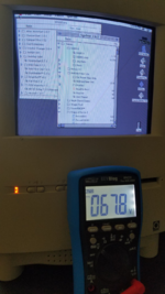 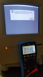 | |
| Posted by: gbcs001 on 2023-03-30 10:28:36 Thanks. I clearly need to get my B+ voltage up to eliminate the raster distortion. If a 500K trimpot doesn't do it, I can substitute a 1k. | |
| Posted by: gbcs001 on 2023-03-30 15:41:22 I made some progress on my Color Classic. I was able to pick away the glue that was preventing me from adjusting the trimpot. I was then able to adjust it to get B+ to 71.0V. The resistances between the pot pins were 372, 372, and 0 ohms (previously the measurements were 517, 517, and 0 ohms). Obviously, I’m not able to determine the trimpot’s value in circuit. It’s likely a 1K pot, as YMK suggested. At the new pot setting the raster distortion was reduced, but not completely. I raised B+ to 71.9V and got pretty good raster after some additional video adjustments on the back. Satisfied with the results, I put the CC back together switched on the AC. I saw a whisp of smoke, and immediately switched off line power. After that, the CC wouldn't boot. A few checks revealed no +12 and +5 voltages from the analog board. Oddly, I didn't see any signs of a burned component on the board. Did I do something wrong putting the CC back together? I don't know. I understand there's no schematic for the CC's AB, so it's going to be a challenge fixing it (sigh). | |
| Posted by: ymk on 2023-03-30 19:15:09 I've gotten smoke before. Several components are underrated and adjusting the geometry or B+ pushes them over the edge. DL21, DL22, RL62, R22 and DF2 all run hot, some enough to scorch the PCB. I've replaced several with much larger components and written about it here. | |
| Posted by: gbcs001 on 2023-03-31 15:55:29 After smoking my CC analog board, I have no +12- or +5-volt outputs to the logic board. Diagnosing the problem is proving to be a good learning experience. Please correct me if I’m wrong, but it looks like the CC’s analog board uses a 4A full-wave bridge rectifier (DP1) on 60Hz AC line voltage. I put the scope on the rectifier’s + and – pins and observed + and – half-wave forms -- 180 deg out of phase I assume. I concluded that the rectifier is good. The minus pin of the rectifier is fed to the Source pin of MOSFET QP7 (IRFBC40), and the positive pin of the rectifier is fed indirectly to a switching controller IC (IP7) which controls the Gate pin on the MOSFET QP7. The MOSFET’s Drain pin is connected to a primary winding (pin 2) of the low voltage (larger) transformer. With the scope I saw a pulsing high frequency voltage superimposed onto the input to pin 1 of the big transformer. That didn’t make sense, so I pulled QP7 out of the board and tested it, found it to be defective (the resistance between the Source and Drain pins is 63 ohms regardless of the Gate voltage. I pulled identical QP1 on the high voltage side to compare and found it to be good. Unfortunately, IRFBC40 is obsolete and unavailable. Has anyone found a substitute that works? | |
| Posted by: gbcs001 on 2023-03-31 16:09:00 MOSFET IRFBC40PBF appears to be identical on specs and available from Mouser. | |
| Posted by: Forrest on 2023-03-31 16:27:46 The PBF at the end of the new Mouser part indicates lead free to be ROHS compliant | |
| Posted by: gbcs001 on 2023-04-12 20:19:24 I'm still trying to find the problem with my Color Classic analog board which I smoked a few days ago. I get no +5 or +12 volts, nor am I producing 22KV to the CRT. While looking for bad components I found what looks like a burned resistor. I remove it and it measured 0.11ohms. What's curious is that it's located on the AB labeled LP14 with a coil symbol as shown in the photo. LP14 is not a component on the list of AB components. Can anyone tell me what the value of this resistor is? The best I can make out the bands is BROWN BLACK BROWN SILVER (100 ohms 10%). Can anyone confirm? | |
| Posted by: ymk on 2023-04-12 20:25:59 L is an inductor, not a resistor. At DC, it will measure close to zero Ohms. | |
| Posted by: gbcs001 on 2023-04-12 20:38:46 Thank you. I didn't know that these tiny inductors have colored bands like resistors. That would make it 100 µH, and probably not faulty. | |
| < 2 |