68kMLA Classic Interface
This is a version of the 68kMLA forums for viewing on your favorite old mac. Visitors on modern platforms may prefer the main site.
| Click here to select a new forum. | |
| Cloning the Interware Booster 30 | |
Posted by: max1zzz on 2022-04-21 14:03:50Have yet to see an Interware card that has GALs that are actually locked. No cracking needed, pretty sure you'll be able to just read it.Yep: 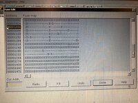 Programmed it back to another GAL and verified the card still works 🙂 One thing we have discovered about this board though is that it doesn't seem to work in the LC, it works just fine in the LC II but produces death chimes on the LC, I did try swapping the LCII ROM into the LC which stops it producing death chimes but the system never actually boots. I wonder if anyone with more low level knowledge might be able to suggest why this might be? | |
| Posted by: mg.man on 2022-04-21 15:19:52 Great stuff on dumping the GAL! produces death chimes on the LC...so at least it wasn't just me. 🤔 Could it be that it will only "boost" a '030? Doesn't the LC I have a '020? | |
Posted by: CC_333 on 2022-04-23 12:50:42I wonder if anyone with more low level knowledge might be able to suggest why this might be?I don't have much low level knowledge of these sorts of things, but I know enough that I can speculate: perhaps it has something to do with the LC's lack of a PMMU? (The '030, and hence the LC II, has a PMMU built in, primarily to facilitate support for System 7's then-new Virtual Memory feature). That's the only major difference between the LC and LC II that I can think of, other than the deletion of the second internal floppy drive option. c | |
| Posted by: max1zzz on 2022-04-24 16:38:48 Now that didn't take too long: 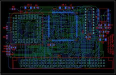 Now I just have to quietly reassemble the original card before @mg.man notices...... 🙂 | |
Posted by: mg.man on 2022-04-24 16:48:24before @mg.man notices...Too late!!! 🤔 | |
| Posted by: djhaloeight on 2022-04-24 21:49:39 Nice work! | |
Posted by: max1zzz on 2022-04-25 13:33:27Too late!!! 🤔 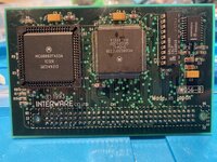 No idea what your talking about..... 🙂 | |
| Posted by: mg.man on 2022-04-26 05:16:26 Well... spot the difference... before...  😉 Seriously, you didn't need to Six Million Dollar Man it - you could've kept the bits off until you have your repro-boards. 🙂 Ooo... speaking of ... what colour pcb are you going for? Also, have you thought about trying for a higher clock? Could that Motorola chip be re-wired to 2.5x the 16Mhz clock? That'd get you just over 40Mhz? 🤔 | |
| Posted by: max1zzz on 2022-04-26 07:55:50 The board is pretty simple and I have good scans of it, I didn't really see any point in leaving it disassembled (And I didn't want to bend the legs on the 68030 either....) Ooo... speaking of ... what colour pcb are you going for?Not sure yet, I was thinking blue to match the repro LC II boards but I had a ultrasonic related incident with a blue JLC board recently so i'm not sure now... maybe red or black? Also, have you thought about trying for a higher clock? Could that Motorola chip be re-wired to 2.5x the 16Mhz clock? That'd get you just over 40Mhz?Yes I have, the clock chip actually runs it's standard output at 2x the input clock, so the 2x output would be 4x the system clock though that is proiabley too fast for even the fastest 030's. I need to look into alternative clock options to hopefully get something more around the 2.5 - 3x mark 🙂 | |
| Posted by: max1zzz on 2022-04-26 09:22:20 This looks like a possibility: https://www.diodes.com/assets/Datasheets/PT7C4511.pdf It's cheap (£1.18 from digikey) and supports 2x, 2.5x and 3x | |
Posted by: mg.man on 2022-04-26 10:09:10maybe red or black?RED would be kinda cool... 🙂 ...as would 40Mhz! Of course, BLACK would mask any scorching! 🤣 | |
Posted by: CC_333 on 2022-04-28 09:13:24Well... spot the difference... before...I notice three differences:
| |
Posted by: mg.man on 2022-04-28 09:19:13the pin holes are round on the reassembled photo, but they're not on the originalI saw that too... I wondered if it was just back-lighting... 🤔 You didn't mention the tants are a totally different color? 😳 😉 | |
Posted by: mg.man on 2022-04-28 09:21:07a few smudges of dust on the PCB, and something that looks like flux residue on the CPUas @max1zzz will confirm... we're both a little Ultrasonic-shy atm... 😕 So I'll let that slide. 🤣 | |
Posted by: CC_333 on 2022-04-28 09:25:06You didn't mention the tants are a totally different color?Ah, yes! I didn't notice that. Good spotting!! c | |
Posted by: max1zzz on 2022-04-28 09:46:28I notice three differences:That's most of them except: You didn't mention the tants are a totally different color?Oh, and a couple of the ceramics have changed form 1206's to 0805's become someone dropped a couple then found they had no 1206's in stock at all..... 🙂 | |
Posted by: mg.man on 2022-04-28 09:48:22a couple of the ceramics have changed form 1206's to 0805'sHow could I have missed that!! 🤣 | |
| Posted by: max1zzz on 2022-04-28 09:54:04 On a more serious note: My plans for this card are to now draw schematics from the sprint layout and redesign the card around a more modern clock multiplier IC as that Motorola part is somewhat hard to get. Hopefully this will also allow the CPU to be clocked a little higher as long as the code in the GAL can handle that. I have a couple of pin compatible alternatives from the chip I linked to above (Which where more expensive but easy to get in the UK) on the way to test this out | |
| Posted by: max1zzz on 2022-05-01 03:37:23 I did a little testing with the clock multiplier I want to use and can confirm it works perfectly at 2x however unfortunately higher speeds won't be possible without further modifications to the design, I tried both 2.5x and 3x with no luch (No chime / activity from the mac at all) I'll modify the design to use this chip anyway since it is easyier to source than the original MC88916 I also got the board transferred from Sprint to Kicad along with a full schematic drawn which will make modifying the card much easyier 🙂 | |
| Posted by: Trash80toHP_Mini on 2022-05-01 08:00:00 So, very, very cool on this one, max. Noticed all components are only on the component side. Will JLPC(?) boards with more than just the teensies pre-installed be possible? Discrete clocking network comes to mind.. Are you switching to socketed CPU, sounds like it. When you do your layout, maybe run all the 030 signals to a PDS passthru? Got notions about implementing that one. 😉 | |
| < 2 > |