68kMLA Classic Interface
This is a version of the 68kMLA forums for viewing on your favorite old mac. Visitors on modern platforms may prefer the main site.
| Click here to select a new forum. | |
| Reverse Engineering the Macintosh LC III Logicboard | |
| Posted by: mmu_man on 2021-08-28 11:32:49 That's what my scope shows here, cf. previous posts. | |
| Posted by: max1zzz on 2021-08-28 14:14:02 Indeed 31.3344 seems to be the correct value, it just seems to be such a odd value to be generating the system clocks from..... I'm wondering if that clock chip is actually internally generating the system clock (Which is stated to be 50mhz in the devnotes, the VLSI divides in by 2 to get the 25mhz CPU clock) and the video / audio clocks and that he crystal is solely used for the serial clock (Which is 31.3344mhz according to the devnotes) Might be intresting to try removeing the crystal form a III and seeing if it still boots.... | |
| Posted by: mmu_man on 2021-08-28 15:14:05 The fact that the overclocking mod changes R14 which is right next to the chip and the quartz and that it makes it go to "33" (but anyone actually measured it?)… I'd bet there's a scaler (or PLL then, if it needs to go to 50) in this chip that is configured by this resistor. | |
| Posted by: mmu_man on 2021-08-28 15:25:12 Google drove me back to 68kMLA 🙃 : Here is the text from the LC III's Developer Note:🤷♂️ | |
Posted by: mg.man on 2021-08-29 04:12:10it's already documented in this articleYes, well, my reason for posting the video with the "hack" was to highlight that the crystal frequency <> the CPU clock frequency... It looks like everyone is on that page now - but the question remains... what *is* that crystal frequency?... Perhaps @Bolle is correct? Anyone know to help out @max1zzz? | |
| Posted by: mg.man on 2021-08-29 04:13:35 Ah... looks like it's in your last post - didn't see it at first, had to "click to expand" 😀 | |
| Posted by: mg.man on 2021-08-29 04:17:46 So... kinda out of my depth here... but if the CPU clock is "generated"... might it be possible to find a combo of resistor config that pumps 40Mhz or even 50Mhz into it and thus build a super-charged LC III++(+)? 😀 I suppose you'd need super-fast RAM / VRAM? | |
| Posted by: max1zzz on 2021-08-29 04:41:43 @mg.man Its might be possible there is, but looking at the schematic it is unlikely, the speed is controlled by a single pair of resistors that pull a signal on the cock chip and vlsi either to ground or 5v there doesn't seem to be any other configuration options | |
Posted by: mg.man on 2021-08-29 04:44:54the speed is controlled by a single pair of resistorsDoesn't that give 4 'possibilities'? I suppose 25Mhz and 33Mhz are two of them... I wonder what the other two combos produce? 🤔 | |
Posted by: max1zzz on 2021-08-29 04:49:24Doesn't that give 4 'possibilities'?Given the config resistors are just 0 ohm links I would advise against installing both at the same time 🙂 There is a mystery chip that can sit between some signals of the clock chip and he vlsi, but it's not clear what that chip could be or what it's purpose was | |
Posted by: mg.man on 2021-08-29 05:34:31I would advise against installing both at the same timeBut are they tied to different input pin? Thus giving a "0" or "1" option for each input? I'm away, so no access to schematics... just thinking "logically"... 😉 | |
| Posted by: cheesestraws on 2021-08-29 05:35:07 Nah, they're both attached to the same pin AIUI. | |
Posted by: mg.man on 2021-08-29 07:27:59they're both attached to the same pinSo how does that work? Does one go to 5V and the other to GND - so that there are three states? "Open", "GND" or "5V"? | |
Posted by: max1zzz on 2021-08-29 07:50:35So how does that work? Does one go to 5V and the other to GND - so that there are three states? "Open", "GND" or "5V"? 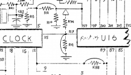 R74 and R14 are the ones your looking at I think it's pretty unlikely the chip will be able to detect a floating pin, and given the chip is likely custom to just this mac (or maybe this one and the 475) it seems unlikely apple would have built in support for running it at a significantly faster clock | |
| Posted by: mg.man on 2021-08-29 07:53:16 Interesting... so you recon it's a case of "force it high" ["1"] or "force it low" ["0"]? | |
| Posted by: mmu_man on 2021-08-29 09:56:10 As explained in the dev notes, the "Omega" chip as they call it is a PLL, which generates different frequencies from a base clock by monitoring the drift of the phase of the clock wrt the base one. The config pin simply chooses one of two built-in multipliers, and I guess it's also connected to the VLSI so as to be probed to detect the model number. It should be possible to make a replacement chip from some PLD/FPGA it seems as it seems it can be done with pure logic. | |
| Posted by: mmu_man on 2021-08-29 09:59:57 If anyone is looking for something to do, I think a website to select PLDs based on pinout compatibility with an existing chip would likely be very useful to many 🙂 | |
| Posted by: 360alaska on 2021-08-30 10:31:00 It would be need if you reformulated the board into an ATX for factor offshoot. | |
| Posted by: max1zzz on 2021-08-30 15:35:44 What the hell Apple! Why are there traces bridging C39 and C37???  And yes, there defiantly where caps installed there on the original board 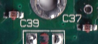 Guess that's two less caps I have to install on the reproduction board 🙂 It would be need if you reformulated the board into an ATX for factor offshoot.It certainly possible and is actually a very interesting idea, a mini-itx board would be really cool, defiantly something to consider for the future! | |
| Posted by: bdurbrow on 2021-08-30 15:50:30 Uhh… how did that even pass automated DRC? | |
| < 2 > |